PCB Assembly for LED Board
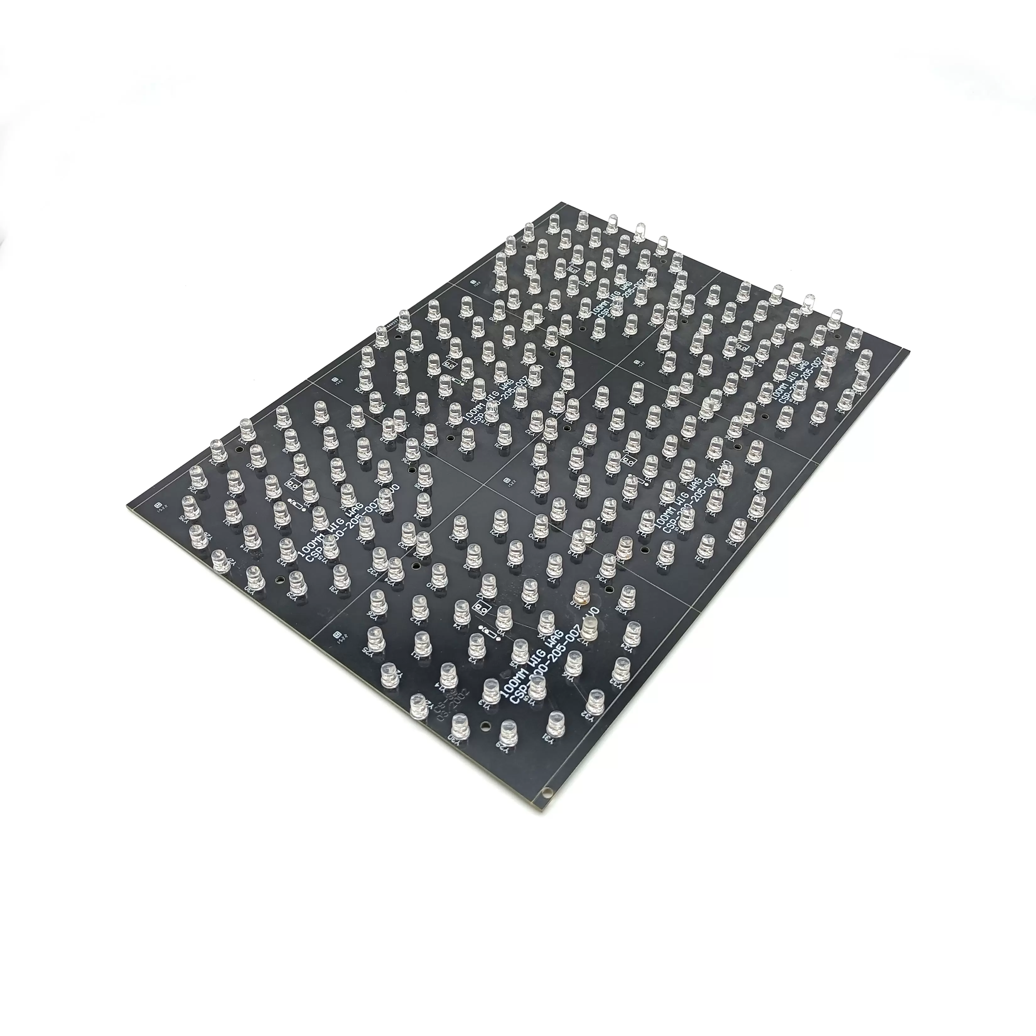
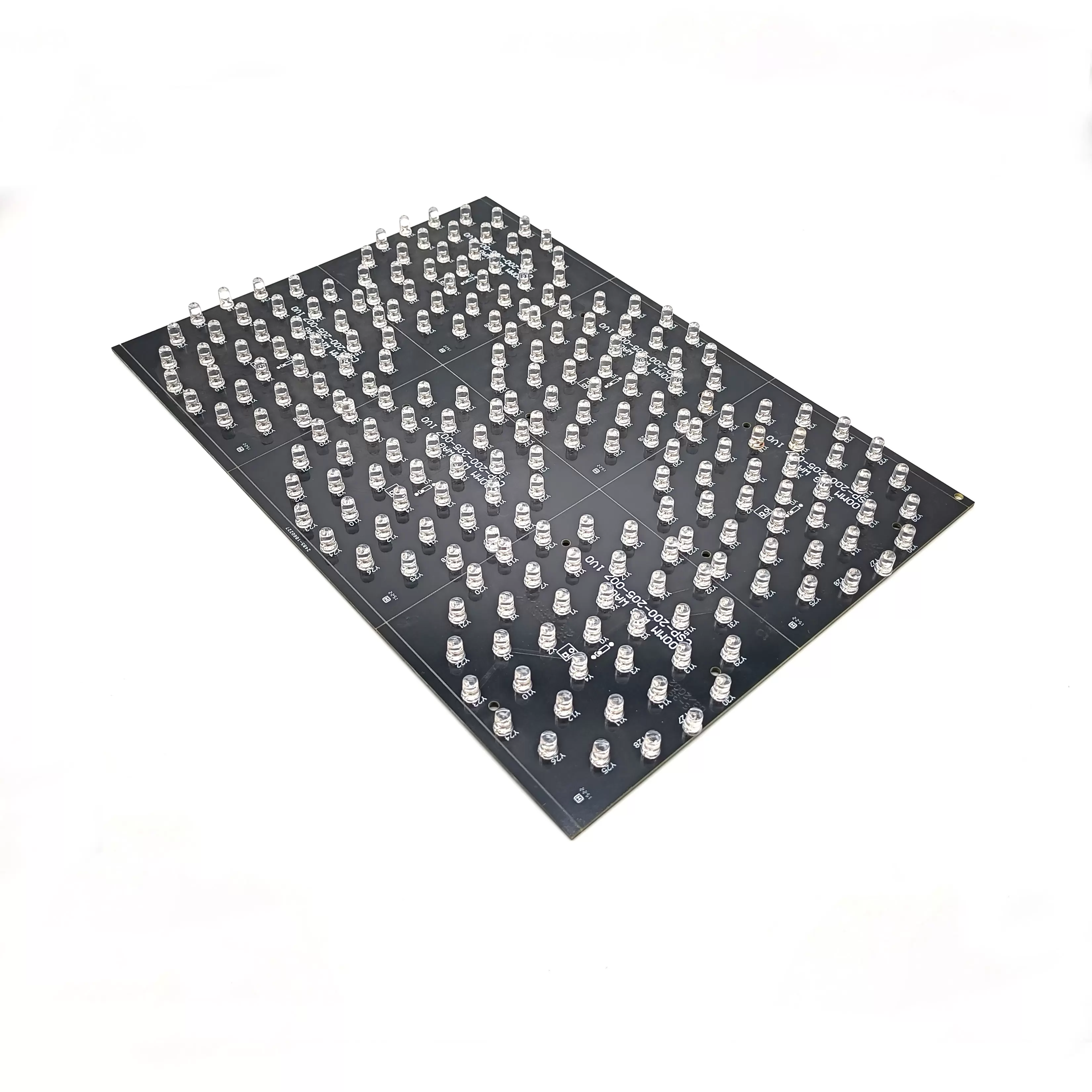
From the layout of this board, it’s clear that the focus is on a high-density LED array, where multiple identical sections are arranged in a consistent grid. This type of structure is typically used when the goal is to achieve stable and uniform light output across a larger surface.
In real applications, PCB Assembly for LED Board is not just about placing and soldering components. Once hundreds of LEDs are working at the same time, even small variations during assembly can start to affect the overall lighting effect.
Uniform Layout Requires Uniform Assembly
The LEDs are evenly spaced, forming a clean matrix across the panel. This kind of arrangement helps keep light distribution consistent, especially in backlight or panel lighting applications.
But in practice, this only works when the assembly process is equally consistent. If not, some common issues may appear:
●Slight differences in LED height affecting light spread
●Uneven solder joints leading to current imbalance
●Visible inconsistency across different areas of the board
For PCB assembly for LED boards, the key is not just making each LED work, but making sure they all behave the same way.
Through-Hole LEDs: More Stable, But Less Forgiving
This board uses through-hole LEDs, which are often chosen for better mechanical strength and durability.
At the same time, they require more control during assembly:
●Insertion depth needs to stay consistent across the whole board
●Wave soldering must remain stable to avoid uneven joints
●Lead trimming should be clean to prevent long-term stress issues
With a layout like this, small deviations don’t stay small—they become visible in the final lighting result.
Black Solder Mask and Light Control
The black surface is not only about appearance. In dense LED layouts, reflections between components can affect how the light looks.
Using a darker solder mask helps to:
●Reduce unwanted light reflection
●Keep the lighting effect more even
●Improve visual clarity in panel applications
This becomes more noticeable as LED density increases.
Thermal Behavior in a Dense LED Board
When many LEDs are operating together, heat builds up across the board over time.
Even with standard materials, a few factors still matter during PCB Assembly for LED Board:
●Solder quality affects how heat transfers from the LED leads
●Uneven joints can create small thermal differences
●Over time, these differences may lead to brightness variation
This is why assembly stability plays a role not just in reliability, but also in long-term lighting consistency.
What Makes the Difference in Production
For this type of LED board, the main challenge is keeping results consistent from one board to another.
That usually comes down to:
●Keeping LED placement uniform across the panel
●Maintaining stable soldering conditions
●Avoiding variation between batches
When these are under control, the board performs more predictably in actual use.
Typical Applications
This kind of PCB Assembly for LED Board is commonly used in:
●Backlight panels
●Display lighting
●Industrial LED modules
●Indicator matrix systems
All of these rely on stable and uniform light output rather than just basic functionality.
PCB Assembly for LED Board is less about the individual components and more about how the whole board performs together.
When assembly is consistent, the LED array delivers stable and even light. If not, small variations quickly become visible in the final result.

 en
en


 WhatsApp