PCB Assembly for Lighting Drive Device
Lighting driver boards don’t usually look complicated, but in real use, they are where a lot of problems start. Heat buildup, unstable current, and early component failure — most of these issues can be traced back to how the PCB was made and assembled.
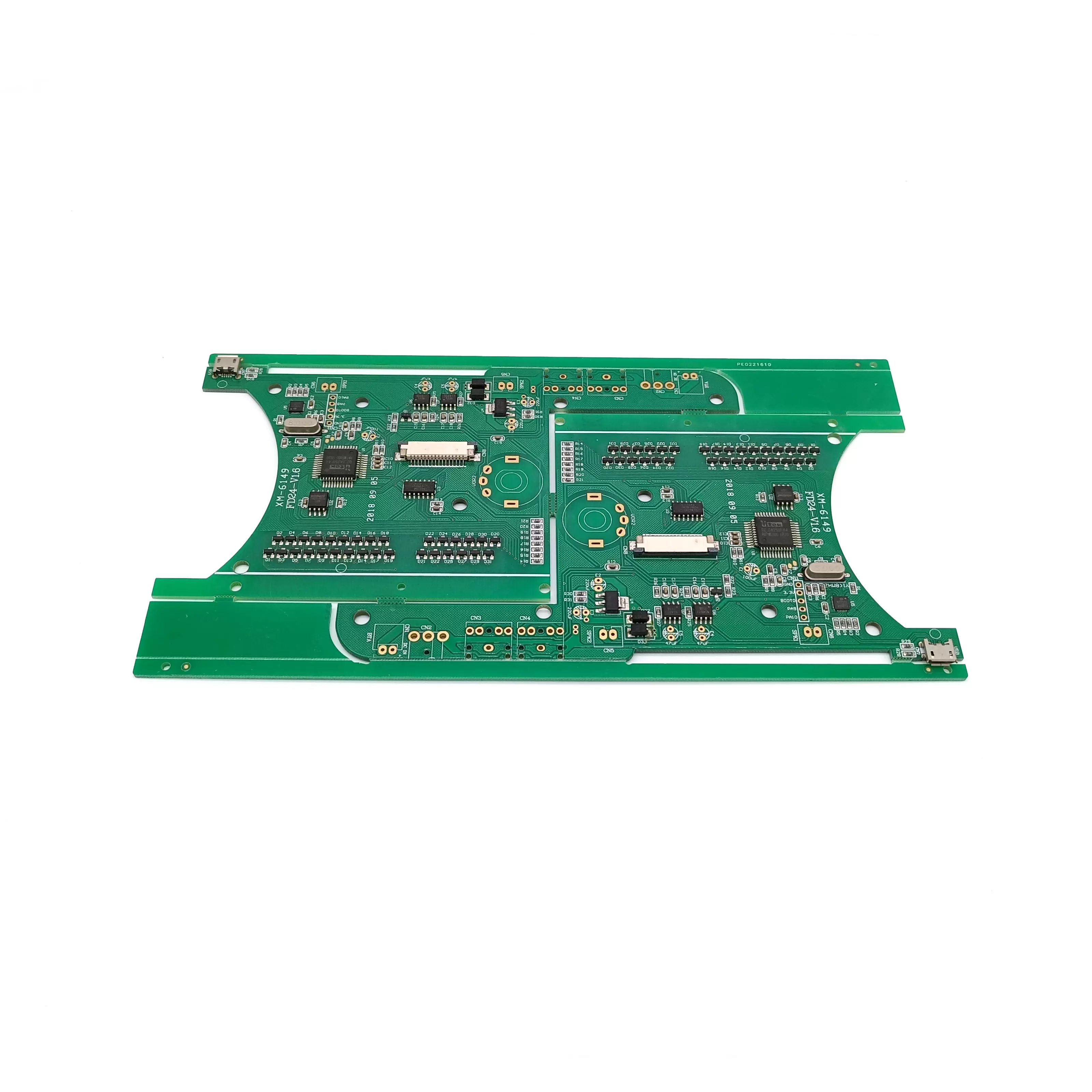
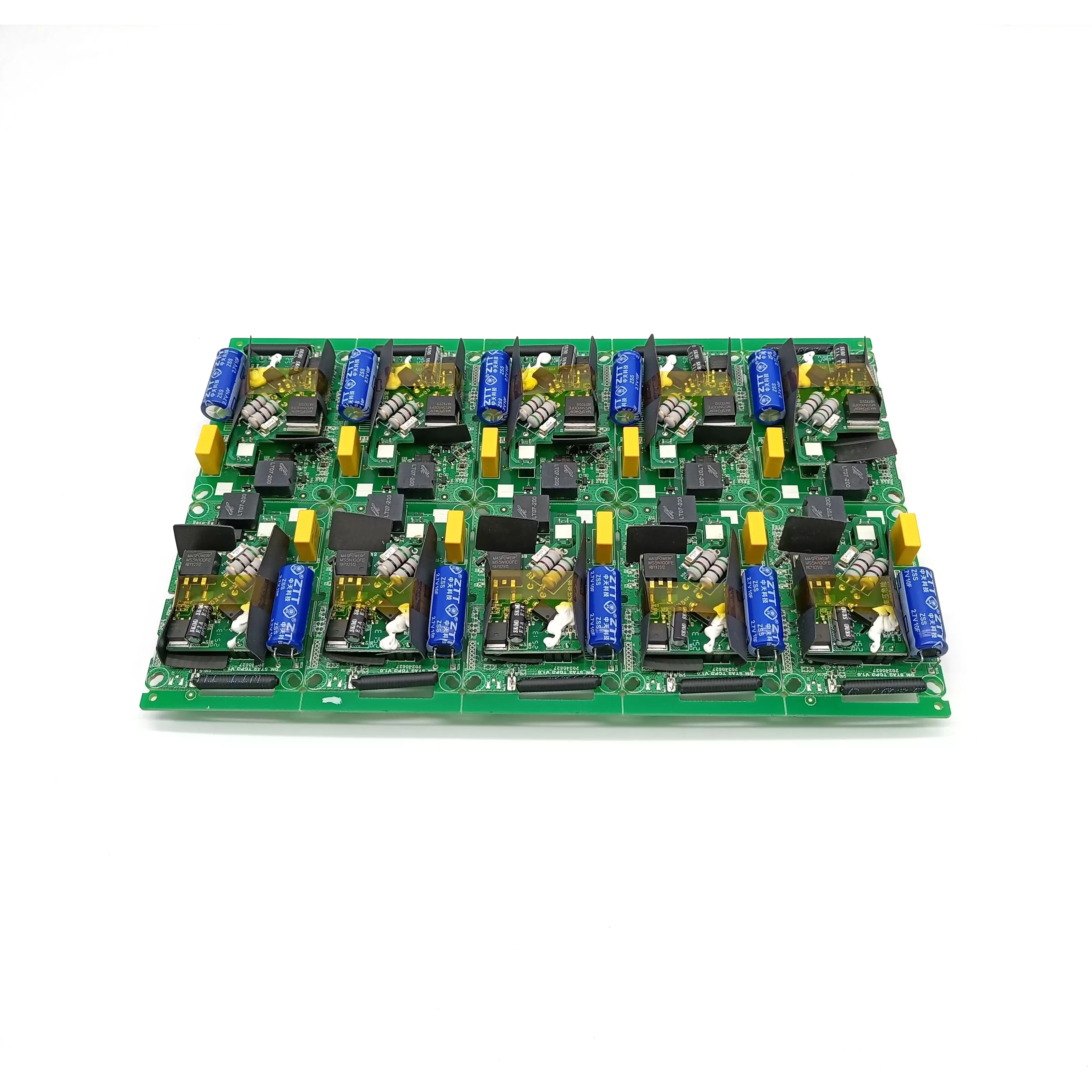
When working on a PCB Assembly for a lighting drive device, the goal isn’t just to get a board produced. What really matters is whether that board can run steadily over time, especially in applications where the lights stay on for long hours or even 24/7.
In many lighting projects, once the driver board goes into the system, there’s little room for adjustment. That’s why more attention is usually given to material selection, soldering quality, and consistency in production, rather than just the basic specs.
Looking beyond the basic specifications
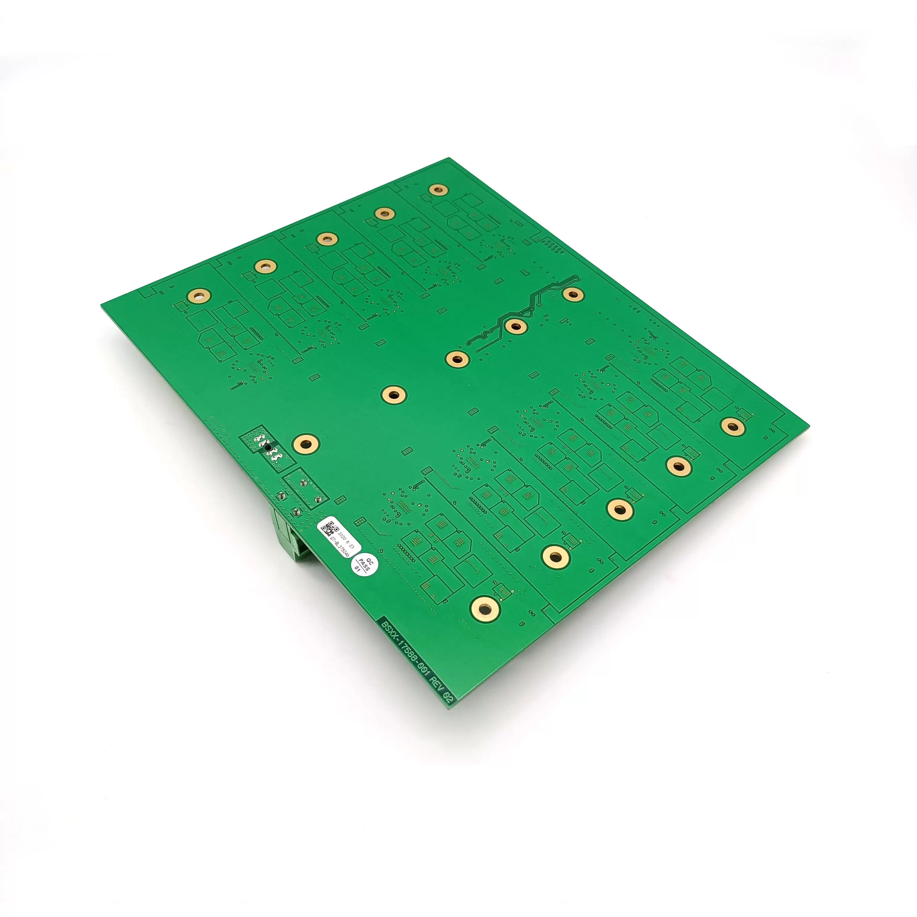
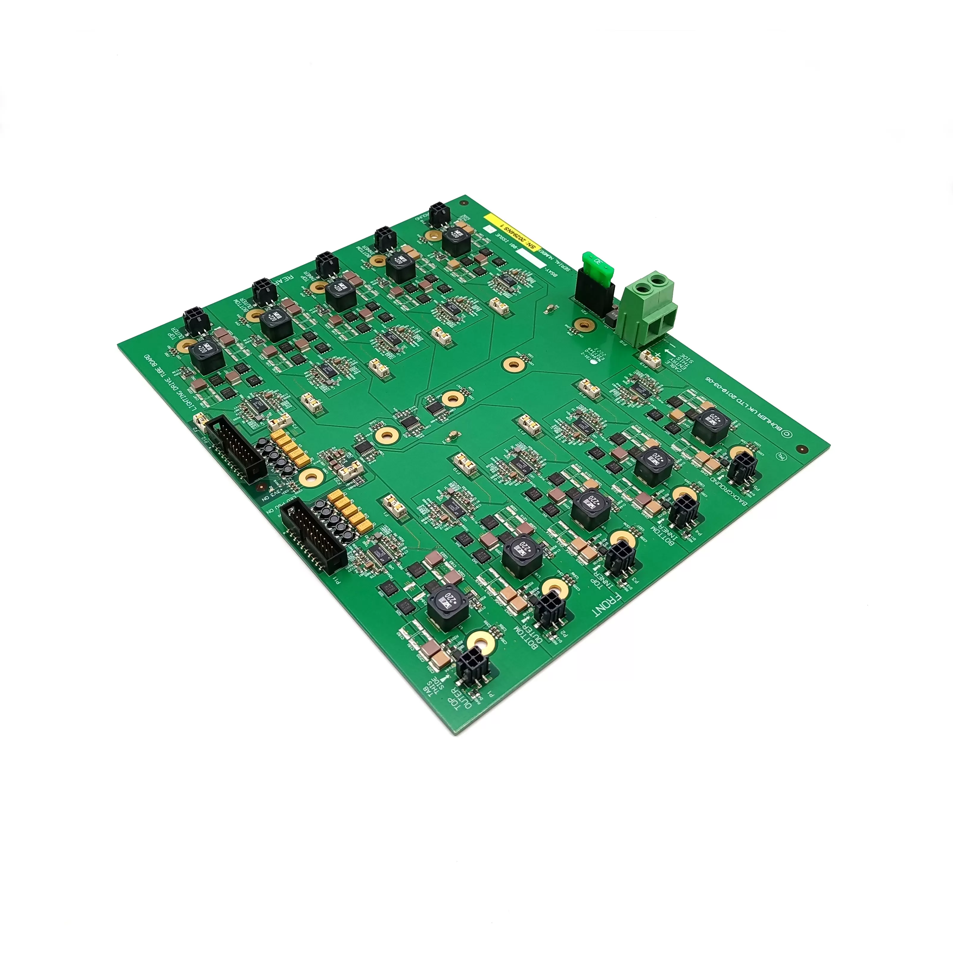
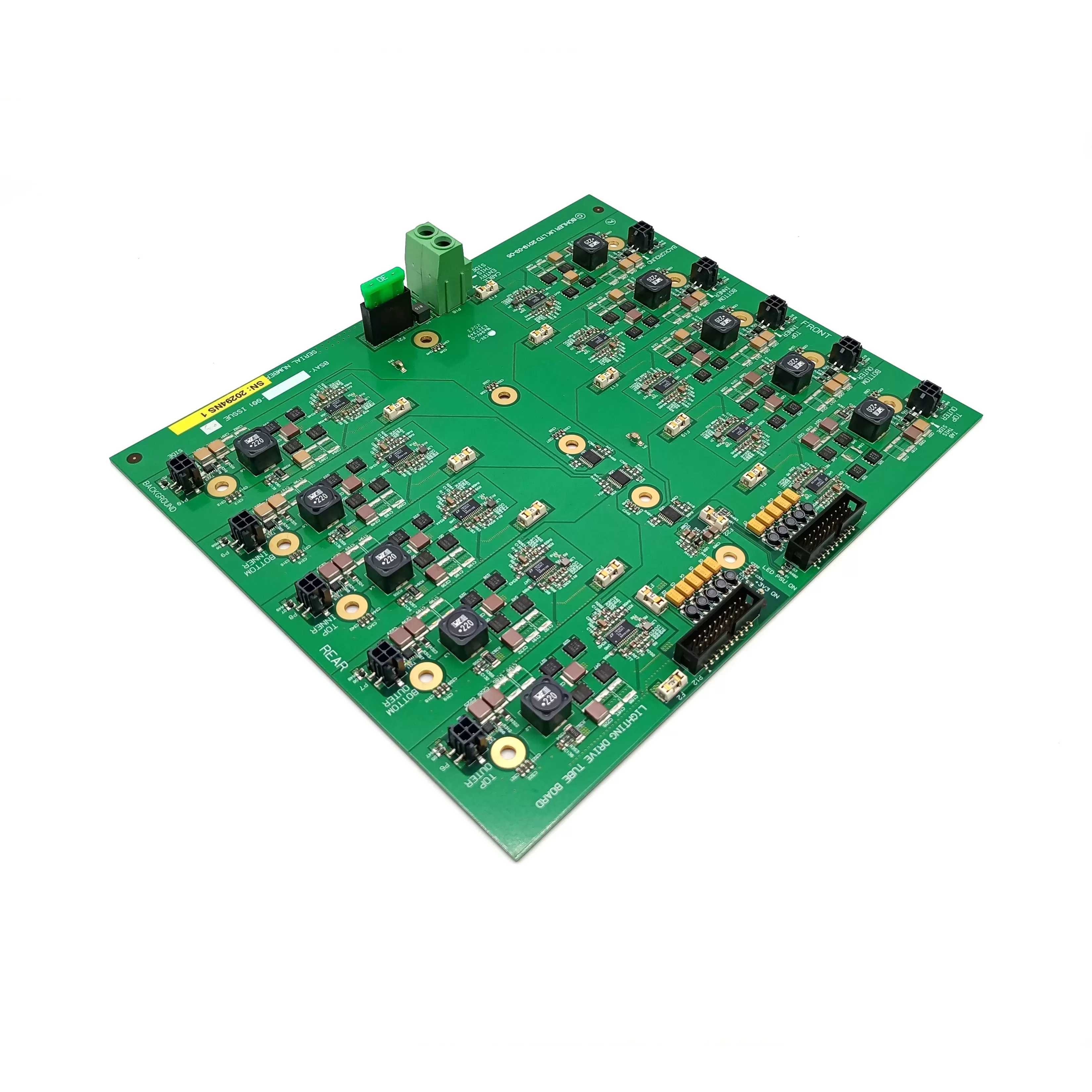
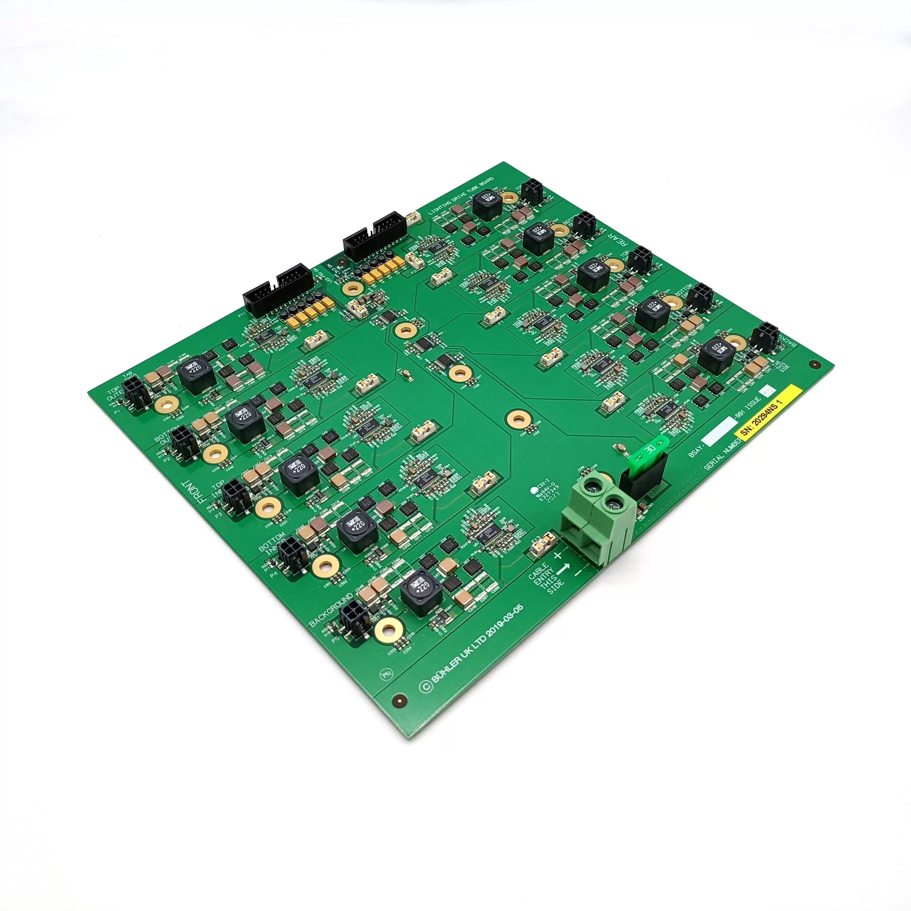
On paper, the configuration of this board is fairly standard. It uses FR-4 TG150 material, a 2-layer structure, and 1OZ copper thickness. These are not extreme parameters, but they are chosen for a reason.
For lighting drivers, temperature stability is more important than pushing limits. FR-4 TG150 offers better performance when the board is exposed to continuous heat. LED drivers naturally generate heat during operation, and over time, lower-grade materials tend to warp or degrade. That’s where the difference starts to show.
The 1OZ copper thickness is also a balanced choice. It provides enough current-carrying capability for most lighting driver circuits without unnecessarily increasing cost. In real applications, what matters is not just how much current the board can handle at peak, but how stable it remains during long-term use.
A 2-layer board keeps things simple and efficient. Most lighting driver designs do not require complex multilayer routing, so keeping the structure straightforward helps with both manufacturability and cost control.
Where reliability usually comes from
In lighting driver boards, failures are often not caused by design flaws, but by small issues in assembly. Solder joints, surface finish, and component placement all play a role in how the board performs after months of use.
This is why ENIG surface treatment is used. It improves solderability and reduces the chance of oxidation over time. For projects that involve outdoor lighting or humid environments, this becomes even more important.
Compared to other finishes, ENIG tends to provide more consistent results during assembly. The solder joints are more stable, and the connection between components and the board remains reliable even after repeated thermal cycles.
These details may not be obvious at the beginning of a project, but they often determine whether a lighting system runs smoothly or starts to show issues after installation.
Typical use in lighting applications
A PCB Assembly for a Lighting Drive Device like this is commonly used across different types of lighting systems. While the environments vary, the expectations are quite similar.
You’ll usually see this kind of board in:
LED street lighting systems, where the board needs to handle outdoor conditions and long operating hours
Commercial indoor lighting, such as offices or retail spaces, where stability and efficiency matter
Industrial lighting setups, where durability is a key concern
Smart lighting systems that integrate control modules along with power drivers
Each of these applications places slightly different demands on the PCB, but the common requirement is reliability over time.
Production is more about consistency than scale.
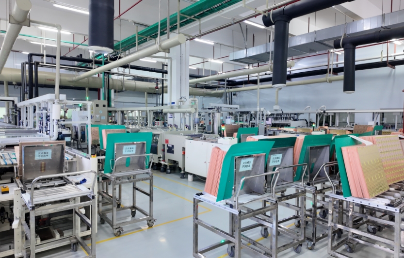
A lot of manufacturers talk about equipment, but from a customer’s point of view, what matters more is whether the boards come out consistently from batch to batch.
For this type of PCB assembly, the focus is usually on keeping the process stable. That includes how components are placed, how soldering is controlled, and how each batch is checked before delivery.
Quick response is also part of the process. Being able to review files and provide feedback early helps avoid problems later. Whether it’s a prototype run or a production batch, catching issues at the beginning saves both time and cost.
Scaling from small quantities to larger volumes should not introduce variation. That’s something that depends more on process control than on the number of machines on the floor.
Quality checks that actually matter
Lighting driver boards are expected to run for long periods without failure. Because of that, testing is not something that can be skipped or simplified too much.
In most cases, a few basic checks are always included:
AOI is used to inspect solder joints and placement
Functional testing verifies that the circuit performs as expected
A final inspection is done before shipment to catch any visible issues
These steps are straightforward, but they help reduce the chances of defects reaching the customer. Over time, consistent testing makes a noticeable difference in product reliability.
Flexibility for different project needs
Not every lighting project is the same. Some require higher power output, others focus on compact design, and some are built for more demanding environments.
Because of this, a PCB Assembly for a lighting drive device is rarely a one-size-fits-all solution. Adjustments can be made depending on the application. Material choices, surface finishes, and assembly processes can all be adapted to better match the project.
Having this flexibility makes it easier to move from design to production without unnecessary delays. It also helps reduce the need for redesigns later on.
In lighting projects, the PCB assembly is not the most visible part, but it has a direct impact on how the entire system performs. Small details in material, soldering, and process control often make the difference between a product that runs reliably and one that needs constant attention.
If you are working on a lighting driver project and need a PCB Assembly for a lighting drive device, it helps to review the design and production approach early. A quick check of the files and requirements can often prevent issues that are harder to fix later.
You can share your Gerber files or project details for evaluation. Even a short discussion at the beginning usually leads to a smoother production process and fewer surprises down the line.

 en
en


 WhatsApp