Smart Pet Locator PCB Assembly
Case Study: Smart Pet Locator PCB Assembly — Engineering Reliable Tracking for Furry Companions
In the growing market of pet tech, smart locators have become essential tools for pet owners, offering peace of mind through real-time tracking. A leading pet electronics brand partnered with us to tackle the unique challenges of assembling PCBs for their next-gen smart pet locators, focusing on GPS/Cellular connectivity, ruggedness, and ultra-long battery life.
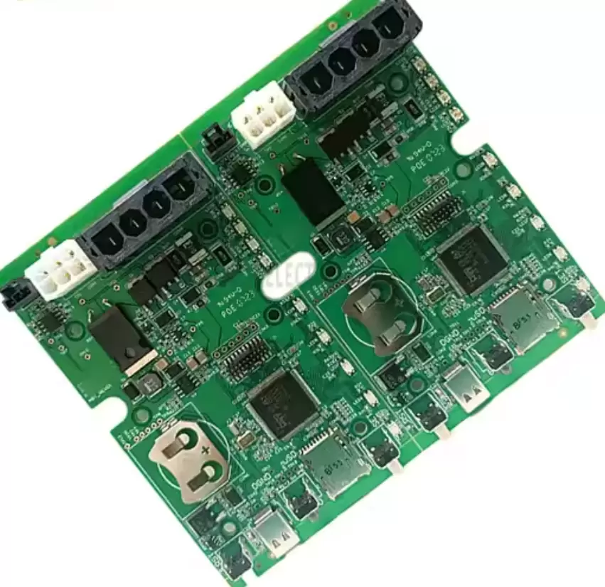
Project Background & Client Requirements
The client’s device is a lightweight (≤20g) pet locator designed to attach to collars, providing global tracking via GPS, LTE-M, and Bluetooth. Its PCB needed to:
· Deliver precise positioning (±2m outdoors, ±5m indoors) with fast satellite acquisition (<30 seconds cold start).
· Withstand harsh pet activities (waterproof to IP67, shock-resistant to 1.5m drops) and extreme temperatures (-20°C to 60°C).
· Operate on a 400mAh lithium battery for 14+ days in standby mode (12-hour tracking intervals) to minimize recharging.
· Meet global wireless standards (CE, FCC, RoHS) for cellular and GPS emissions.
· Scale from prototype (300 units) to mass production (30,000 units/quarter) with consistent reliability.
Key Challenges in Smart Pet Locator PCB Assembly
The project presented distinct hurdles tied to the device’s small size and demanding use cases:
1. Mixed Connectivity Sensitivity: Integrating GPS (1.575GHz), LTE-M (850/1900MHz), and Bluetooth (2.4GHz) in a compact space risked signal interference, degrading tracking accuracy.
2. Miniaturization vs. Durability: Packing a GPS chip, cellular module, battery management IC, and sensors into a 25mm×15mm PCB while ensuring solder joints could withstand drops and water exposure.
3. Ultra-Low Power Constraints: Even minor inefficiencies in PCB traces or component soldering could drain the small battery, reducing standby time below the 14-day target.
4. Environmental Resilience: The PCB needed to resist corrosion from pet sweat, rain, and dirt without compromising electrical performance.
Our Tailored Assembly Solutions
To address these challenges, we developed a “connectivity-first + rugged design” approach combining RF optimization, precision assembly, and environmental testing:
1. PCB Design & RF Coexistence Optimization
· Layout Engineering: Collaborated with the client to minimize signal interference:
· Segregated GPS, LTE-M, and Bluetooth circuits with grounded copper shields to isolate their frequency bands.
· Optimized GPS antenna trace length (≤30mm) and impedance (50Ω) to reduce signal loss, while placing the LTE-M antenna at the opposite end of the PCB to avoid cross-talk.
· Material Selection: Used a 4-layer high-Tg (160°C) FR-4 substrate with 1oz copper and a hydrophobic solder mask (IPC-SM-840) to enhance water resistance. The PCB edges were sealed with conformal coating to prevent moisture ingress.
· Power Management Layout: Designed dedicated low-power paths for the MCU and sensors, with wide (0.3mm) power traces to minimize resistance and reduce energy loss.
2. Precision Assembly for Compact, Rugged Performance
· Solder Paste & Component Placement:
· Used a laser-cut stencil (0.1mm thickness) with micro-apertures to apply solder paste accurately on 0201 passives and the 0.5mm-pitch LGA GPS chip, ensuring no bridging in the dense layout.
· Deployed Juki RS-1R pick-and-place machines with vision alignment (±1μm accuracy) to place tiny components, including a 3-axis accelerometer (for motion-triggered tracking) and low-power MCU.
· Soldering for Durability:
· Applied lead-free solder (Sn96.5Ag3Cu0.5) with a modified reflow profile (peak 245°C) to create strong, vibration-resistant joints. X-ray inspection verified BGA and LGA solder void rates <3% for reliable connectivity.
· Hand-soldered the flexible battery connector with strain relief (reinforced with epoxy) to prevent detachment during drops.
3. Rigorous Testing & Reliability Validation
· RF Performance Testing:
· Conducted GPS accuracy tests in urban and rural environments, verifying ±1.8m outdoor precision and ±4.5m indoor accuracy (using assisted GPS).
· Tested LTE-M signal strength (RSRP ≥-105dBm) and Bluetooth range (≥10m) to ensure seamless connectivity with the owner’s smartphone.
· Power Efficiency Testing:
· Measured standby current (<5μA) and tracking-mode current (<30mA) using a precision multimeter, confirming the 14-day battery life target.
· Validated the battery management system (BMS) via charge/discharge cycles (500 cycles) to ensure safe, efficient power usage.
· Environmental & Durability Testing:
· IP67 testing: Submerged the PCB in 1m of water for 30 minutes, then verified no corrosion or short circuits.
· Drop testing: 50 drops from 1.5m onto concrete (simulating collar impacts), followed by functional checks to ensure no component detachment or signal loss.
· Temperature cycling: Exposed the PCB to -20°C to 60°C (500 cycles) to test solder joint integrity and battery performance in extreme weather.
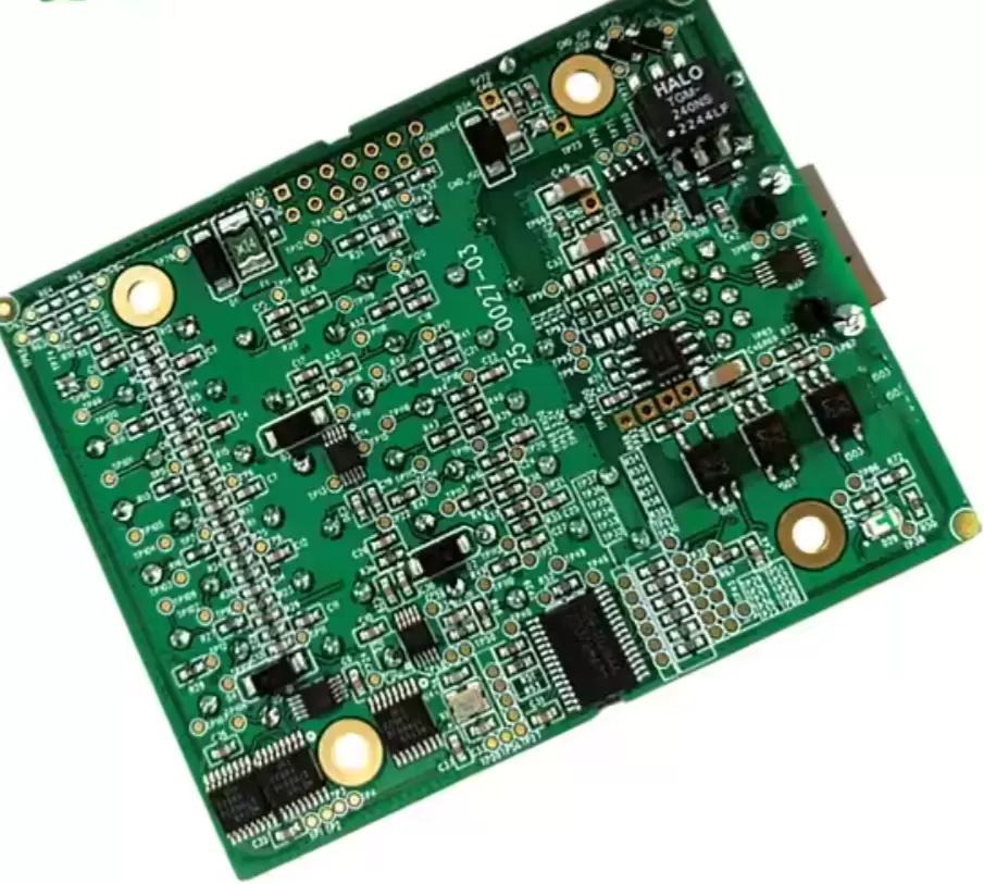
Project Outcomes & Client Impact
· Tracking Precision: The PCBs enabled the locator to achieve consistent ±2m outdoor accuracy and reliable indoor tracking, exceeding the client’s targets.
· Battery Performance: Standby time reached 16 days (384 hours) in testing, with tracking mode lasting 72 hours—boosting customer satisfaction with fewer recharges.
· Production Scalability: Scaled from 300 prototypes to 30,000 units/quarter with a 99.4% yield, supported by automated AOI and X-ray inspection that reduced defect rates.
· Durability Validation: The locator passed all environmental tests, with field trials showing 0% failure rates after 6 months of real-world pet use (dogs, cats, small animals).
Why Choose Us for Smart Pet Locator Assembly?
Smart pet locators demand expertise in RF coexistence, miniaturized rugged assembly, and low-power design—areas where our 14-year focus on precision PCB assembly excels. We understand that these devices are trusted to protect beloved pets, so we prioritize reliability, connectivity, and durability in every step.

 en
en




 WhatsApp