 en
en
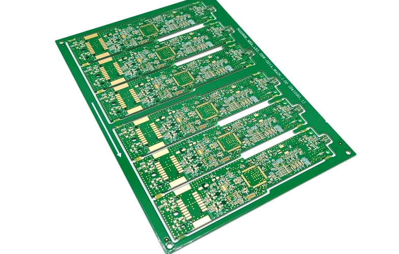
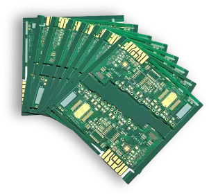
PCB Fabrication Service
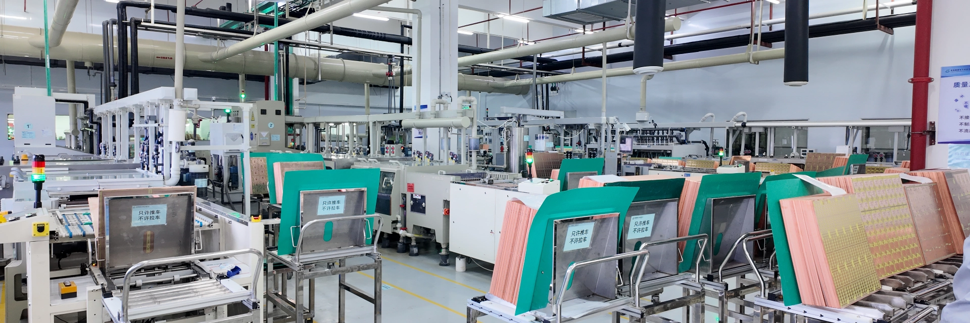
Advanced Equipment, Building High-Reliability PCBs
| Layer | 1, 2, 4, 6, 8 up to 32 layers (Rigid PCB up to 32 layers, FPC up to 8 layers, Rigid-flex PCB up to 16 layers) |
| PCB Materials | FR-4, CEM-1, CEM-3, Hight TG, FR-4, FR-1, FR- 2, Rohs compliant, Aluminum, High Frequency PCB S1000-2, Rogers, Isola 370HR, FPCB, etc |
| Material Manufacturers | SYTECH, TUC, Rogers, Panasonic, Isola, Taconic |
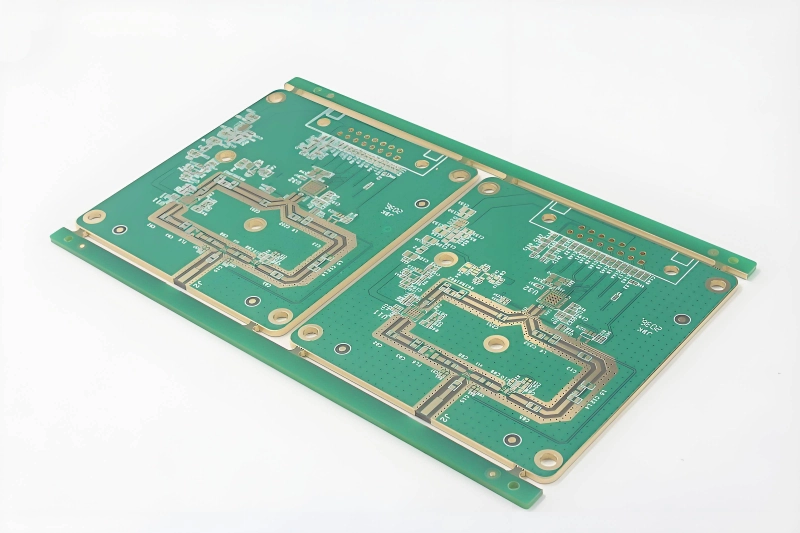
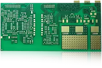
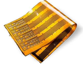
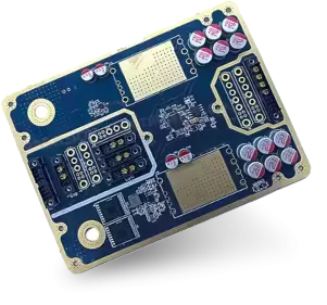
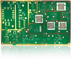
| Category/Types | Rigid PCB, Flexible PCB, Rigid- flexible PCB, Ceramics, HDI, High Frequency, Heavy-Copper, LED/Aluminum |
| Board Thickness | 0.2mm-8mm |
| Maxium Board Size | 550mm* 550mm |
| Minimum Drill Hole Diameter | 0.15mm |
| Minium Line Width | 0.05mm |
| Minium Line Space | 0.05mm |
| Surface Finish/Treatment | HASL/HASL Lead-Free, ENIG, Chemical Tin, Chemical Gold, Immersion Silver, Immersion Tin, OSP, Gold Plating, Golden Finger |
| Copper Thickness/Weight | 1/3OZ, 1OZ, 2OZ, 3OZ, Max 6OZ |
| Solder Mask Color | Green, Blue, Black, Yellow, Red, etc, Matte with colors |
| Vias Tolerance | PTH:±0.076, NTPH:±0.05 |
| Minimum Solder Mask Dam | Width 0.1mm |
| Profiling | Routing, V-Cutting, Grooving |
| PCB Shape | Any shape: Rectangular, round, slots, cutouts, complex, irregular, etc |
| Min.Size of Legend/Silkscreen | Hight 0.8mm, Width 0.13mm |
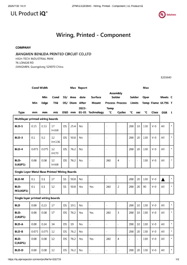
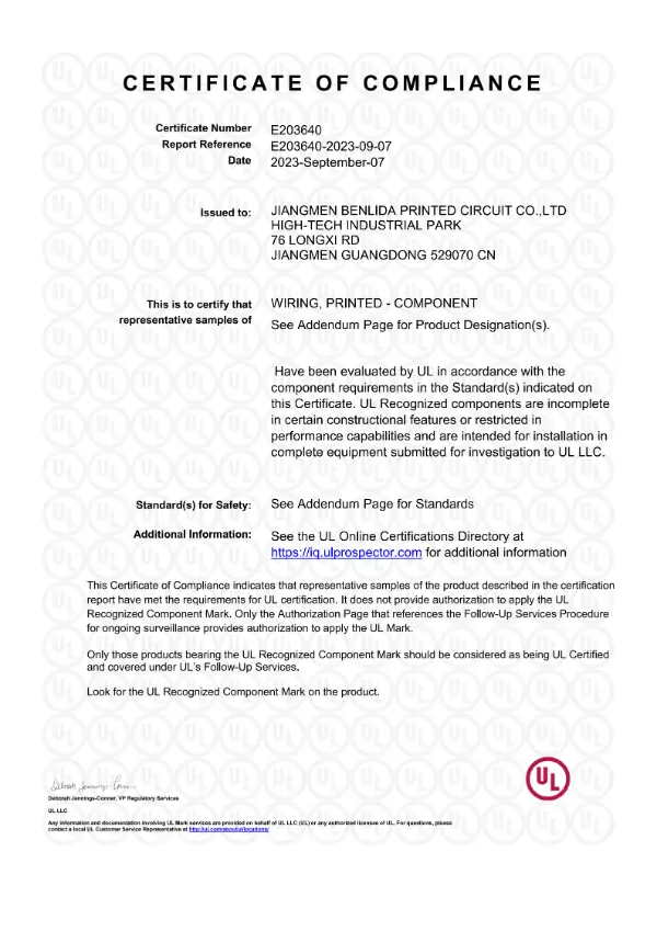
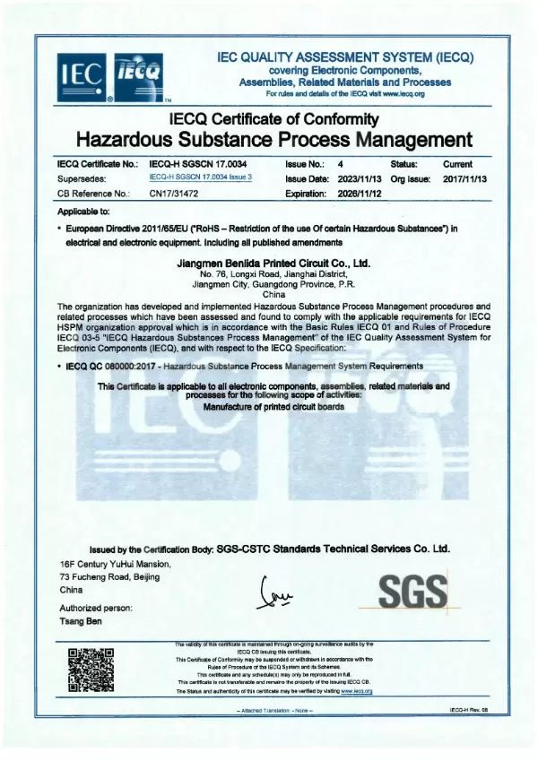
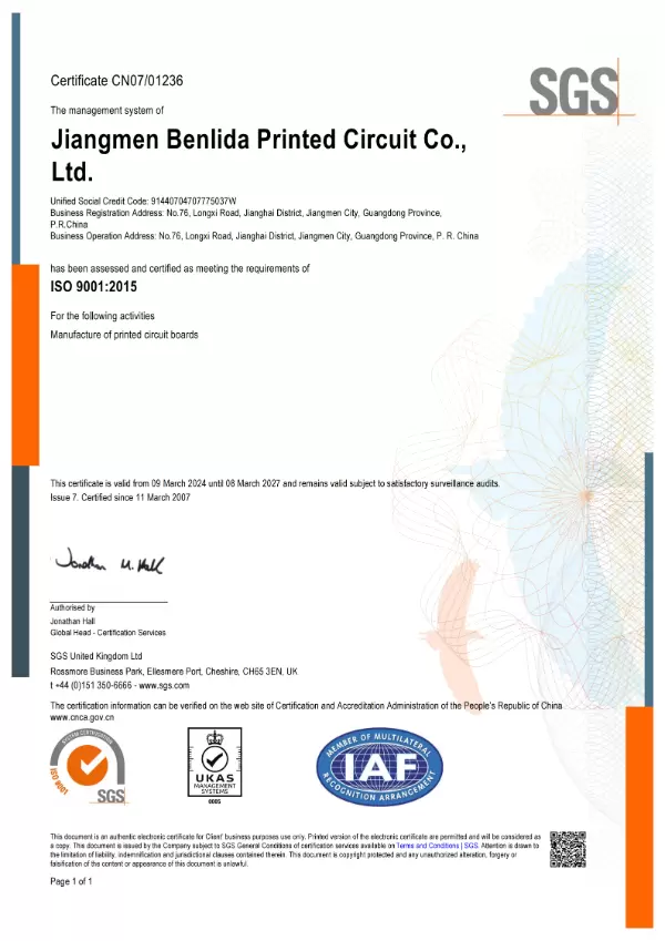
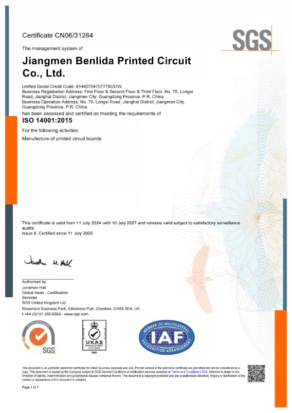
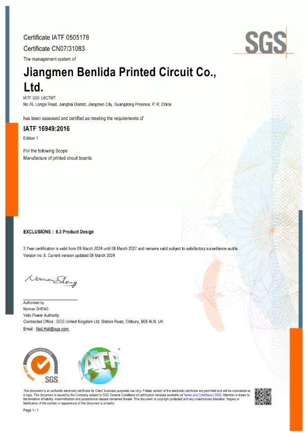
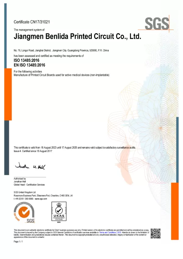
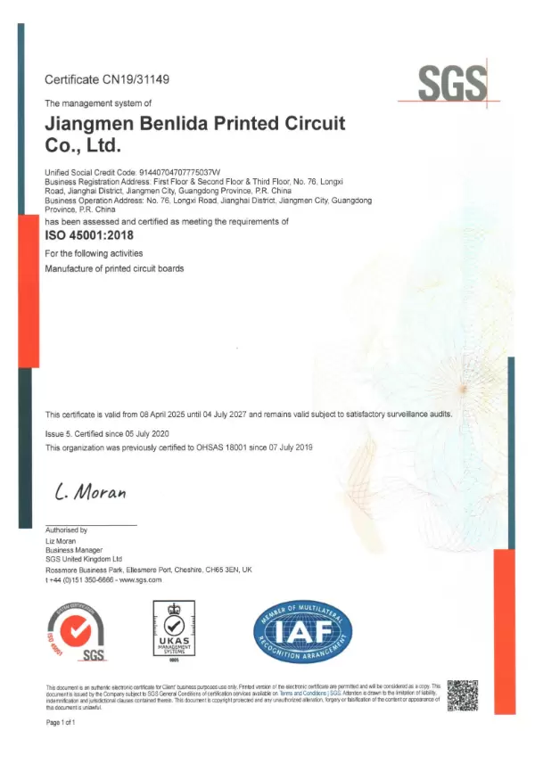
| Certificates | ISO9001, ISO13485, IATF16949, ROHS, CQC, ANSI/ESD |
| Standard | IPC-A-610 |
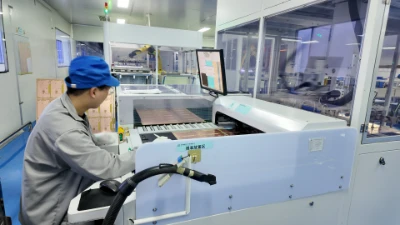
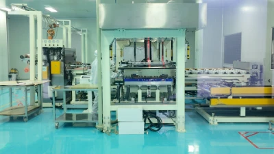
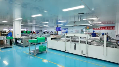
Preparation and Cutting |
Inner Layer Etching |
AOI after Etching |
Lamination |
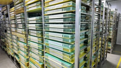
Testing Fixture Storage |
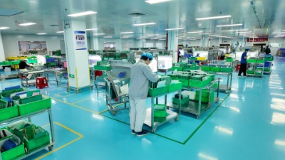
Appearance Inspectation |
Packaging |
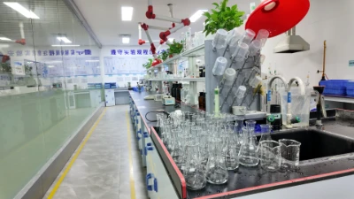
Chemical&Physical Lab |
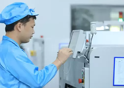
Our quality is built on IPC-A-610 certified workmanship and verified by AOI & X-Ray inspection for every batch. We enforce strict incoming component inspection and a rigorous 5-step quality check workflow, ensuring full traceability and providing detailed test reports for complete confidence.
√ IPC-A-610 certified workmanship
√ AOI & X-Ray for every batch
√ Strict incoming component inspection
√ 5-step quality check workflow
√ Full traceability & test reports
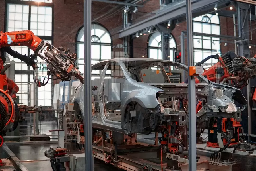
| Industrial Automotive Our high-reliability PCBs, including thick copper and advanced HDI boards, ensure stable performance under extreme temperatures and vibrations. They are ideal for critical applications like engine control units (ECUs), sensors, and onboard chargers, meeting stringent automotive-grade standards. |
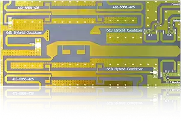
Telecommunications Our high-frequency & high-speed boards and hybrid laminate boards are engineered for superior signal integrity and minimal loss. They are essential for 5G infrastructure, base station antennas, optical modules, and network switching equipment, enabling faster and more reliable data transmission. |
|
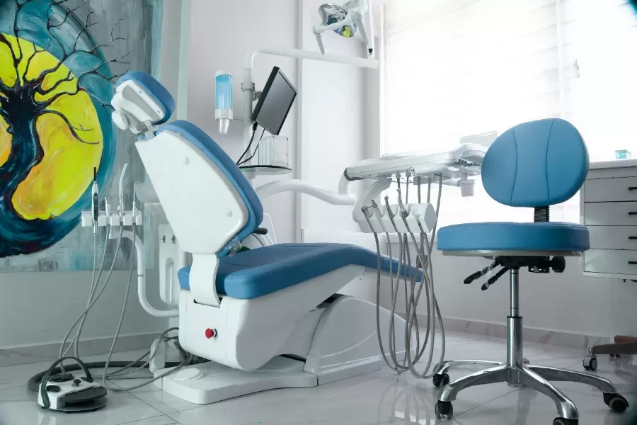
| Medical We provide precision PCBs with excellent biocompatibility and reliability for demanding medical environments. Our products are used in patient monitoring systems, diagnostic imaging equipment, portable medical devices, and surgical instruments, where accuracy and safety are paramount. |
New Energy Our PCBs with thick copper process and high-power design excel in efficiency and heat dissipation. They are key components in solar/wind power inverters, battery management systems (BMS), charging piles, and energy storage solutions, supporting the stable conversion and management of green energy. |
|
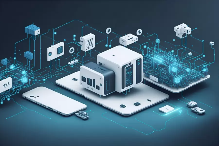
| IoT We specialize in compact, reliable, and cost-effective PCB solutions for diverse IoT devices. Our rigid-flex and precision multilayer boards enable miniaturization and stable connectivity in smart sensors, wearables, gateways, and smart home appliances. |
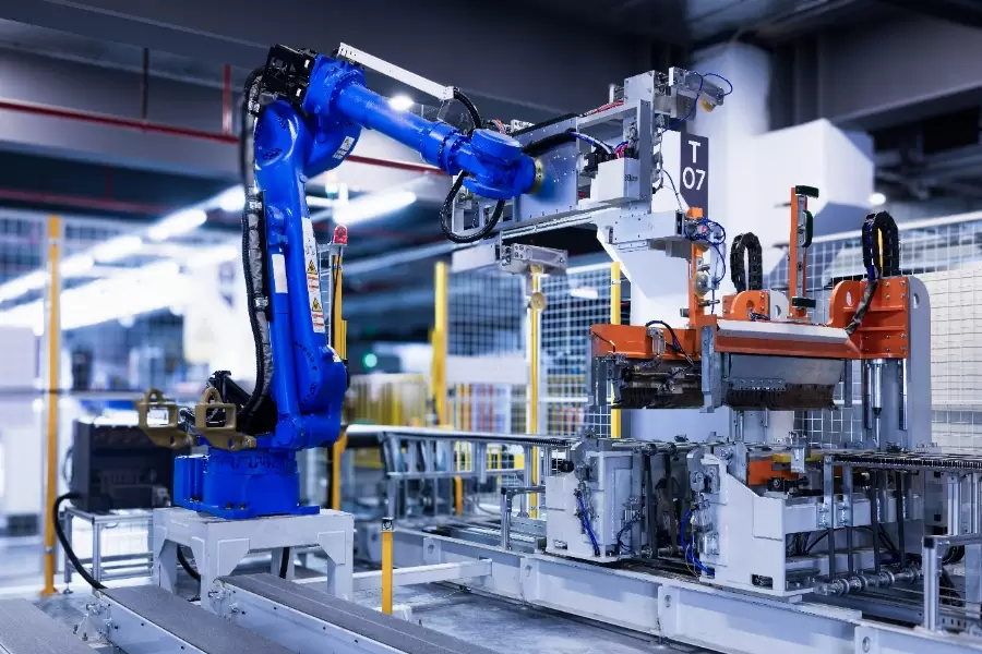
Robotics Our high-density interconnect (HDI) and rigid-flex boards offer the durability, precision, and space-saving features required for advanced robotics. They are used in control boards, motion sensors, vision systems, and robotic joints, ensuring precise control and reliable operation. |
|
| Consumer Electronics We deliver high-quality, fast-turnaround PCBs that balance performance and cost. Our products support a wide range of consumer goods, from smartphones and laptops to gaming hardware and audio devices, helping brands bring innovative products to market swiftly. |
Others Our flexible manufacturing platform and expertise in special processes (e.g., resin plugging, metalized half-hole) allow us to support innovative applications in aerospace, defense, security, and emerging technologies. We collaborate with customers on R&D for custom solutions. |
|
Start Your PCBA Assembly Process Today – Fast Quote in 1 Hour.


 WhatsApp