Multi-layer PCB stack-up design drives high-performance electronics in 2026 with several key trends. Manufacturers focus on HDI adoption, advanced materials, signal integrity, and EMC improvements. AI-driven automation transforms PCB design, enabling faster workflows and reducing errors. Sustainability shapes printed circuit boards as eco-friendly processes gain traction. These innovations improve performance, reduce signal loss, and optimize manufacturability in multilayer PCB projects. Market growth reflects strong demand, and designers prioritize low dielectric constant materials, optimized layer counts, and new via technologies. High-performance electronics benefit from shorter trace lines, efficient power delivery, and minimized EMI.
Multi-layer pcb stack-up design empowers innovation by balancing performance, cost, and reliability in modern electronics.
●Low dielectric constant materials minimize delays and support high-performance electronics.
●Optimized stack-ups lower fabrication costs and enhance performance.
●Blind and buried vias improve signal integrity, supporting high-performance electronics.
Key Takeaways
1. Low dielectric constant materials enhance performance by reducing signal delays in high-speed electronics.
2. Optimized stack-ups lower production costs while improving overall PCB performance.
3. Implementing blind and buried vias boosts signal integrity, crucial for high-performance applications.
4. AI-driven automation streamlines PCB design, reducing errors and speeding up workflows.
5. Sustainable practices in PCB design lead to eco-friendly materials and processes, benefiting the environment.
Advanced Materials in PCB Stack-up
High-Speed Material Choices
Modern electronics rely on advanced stackups that use high-speed materials to achieve optimal PCB performance. Designers select materials based on dielectric properties, loss tangent, and compatibility with high-frequency signals. The table below shows common high-speed materials used in PCB stackup design:
| Material Type | Dielectric Constant (Dk) | Loss Tangent (Df) | Additional Properties |
|---|
| FR4 | 4.3 - 4.8 | 0.015 - 0.02 | Good electrical properties, cost-effective, widely used |
| BT-Epoxy | N/A | N/A | Thermal stability is used in organic chip packages |
| Polyimide | Low Dk | Low Df | Used for high-frequency applications |
| Cyanate Ester | Low Dk | Low Df | Selected for specific performance needs |
| Rogers | 2.2 - 3 | 0.001 - 0.003 | High-frequency applications, low loss |
Designers choose low dielectric constant materials for stackup to support high-speed PCB applications. These materials reduce signal delay and improve data transmission rates. Low-loss laminates such as Rogers and PTFE help maintain signal integrity in advanced stackups. High-speed stackup design also requires careful control of dielectric thickness and copper surface roughness. Microstrip and stripline routing topologies further enhance stackup performance.
Tip: Selecting the right high-speed material for pcb stackup can minimize electromagnetic interference and crosstalk, which are common challenges in dense designs.
Thermal and Low-Loss Substrates
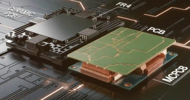
Thermal management is essential for PCB stackup design in high-speed electronics. Designers use substrates with high thermal conductivity to dissipate heat efficiently. The following table compares thermal conductivity values for common substrates in a stackup:
| Substrate Type | Thermal Conductivity (W/m·K) |
|---|
| FR-4 | 0.3 - 0.5 |
| Ceramics | 20 - 200+ |
| Metal-core substrates | 20 - 200+ |
Low-loss substrates play a critical role in stackup by minimizing signal attenuation. These materials are vital for high-frequency PCB applications. Higher dissipation factors lead to greater signal loss, so designers prioritize low-loss laminates in stackup. Smart grids and power transmission systems benefit from low-loss PCB materials, which ensure minimal energy dissipation. Efficient heat transfer in stackup is achieved by implementing thermal vias, heat sinks, and thermal pads.
Note: Advanced stackups with thermal and low-loss substrates improve pcb reliability and longevity by reducing overheating and signal degradation.
Material Impact on Stack-up Performance
Advanced stackups use materials that directly affect PCB performance, reliability, and manufacturability. The table below highlights key benefits of materials used in stackup design:
| Material Type | Key Benefits | CTE (ppm/°C) | Thermal Conductivity (W/m·K) | Moisture Resistance (Water Absorption) | Reliability Improvement (%) |
|---|
| High-Tg Laminates | Improved thermal management, but compatibility issues with manufacturing | N/A | N/A | N/A | N/A |
| Metal-Core PCBs | Closer to CTE and semiconductors, exceptional thermal conductivity | Aluminum: 23 | 150-200 | N/A | N/A |
| | Copper: 17 | 380-400 | | |
| Liquid Crystal Polymers | Low CTE, excellent electrical properties, and moisture resistance | 4-8 | N/A | <0.04% | N/A |
| Stress-Absorbing Adhesives | Accommodate CTE differences, improve reliability metrics | N/A | N/A | N/A | 30-50 |
Stack-up design faces several challenges when implementing advanced materials. Crosstalk can occur when signals interfere with each other, but increasing spacing or adding ground planes in the stackup reduces this issue. High-density PCB designs may overheat, so materials with better thermal conductivity and thermal vias help manage heat. Signal delay results from longer traces or improper layer placement in the stackup, so keeping critical traces short improves performance. Manufacturing defects such as misalignment or warping can arise, but designing with symmetry and consulting manufacturers ensures stackup reliability.
- Specialized low-loss laminate materials like PTFE or Rogers minimize losses in stackup.
- Precise routing topologies, such as microstrip or stripline, are crucial for stackup performance.
- Optimized dielectric properties in substrate materials enable reduced signal attenuation and improved integrity in the stackup.
Advanced stackups address high-frequency operation and thermal management challenges in PCB design. Designers select materials that support high-speed signals, efficient heat dissipation, and reliable performance. These choices ensure that stackup meets the demands of modern electronics.
Signal Integrity and EMC in Stack-up Design
Signal Integrity Stack-up Strategies
Signal integrity stands at the core of modern PCB stack-up design. Engineers must ensure that every signal reaches its destination without distortion or loss. High-speed signal transmission in 5 G devices demands precise control over impedance, crosstalk, and noise. The following table outlines the most effective strategies for improving signal integrity in multi-layer PCB designs:
| Strategy Type | Description |
|---|
| Impedance Control | Target 50Ω single-ended or 100Ω differential using microstrip or stripline configurations. |
| Ground Plane Optimization | Use continuous ground pours with at least two full grounds to partition noise domains. |
| Crosstalk Reduction | Space parallel traces greater than 3h and route orthogonally across layers to minimize coupling. |
Engineers use impedance control to match the signal path to the source and load. This approach reduces reflections and maintains signal integrity. Ground plane optimization creates a stable reference for signals, which is essential for high-speed PCB applications. Crosstalk reduction techniques, such as increasing the spacing between traces and routing them at right angles across layers, help prevent unwanted signal coupling.
Tip: Consistent impedance and careful ground plane design improve signal integrity and reduce the risk of errors during testing.
Testing plays a crucial role in verifying signal integrity. Engineers use time-domain reflectometry and eye diagram analysis to check for signal loss, distortion, and noise. These testing methods help identify weak points in the PCB stack-up and guide further improvements.
Power Delivery and Layer Optimization
Power delivery in multi-layer PCB stack-ups requires careful planning. Engineers arrange signal, ground, and power layers to support both performance and integrity. Layer optimization enhances power delivery and reduces noise by providing low-impedance return paths for signals. The following arrangement demonstrates an effective stack-up for high-speed PCB designs:
- Layer 1: Signal (High-Speed Data)
- Layer 2: Ground
- Layer 3: Power
- Layer 4: Signal (Control Lines)
This configuration ensures that high-speed signals on Layer 1 have a direct reference to the ground plane on Layer 2. The result is improved signal integrity and reduced noise. Engineers also use continuous ground planes to avoid splitting, which can disrupt return paths and create noise. Stitching vias connects ground planes across layers, ensuring a consistent reference for signals.
- Layer optimization techniques enhance power delivery and reduce noise by strategically placing signal, ground, and power layers.
- Ground planes adjacent to signal layers provide low-impedance return paths, crucial for maintaining signal integrity and minimizing electromagnetic interference.
- Continuous ground planes and proper layer arrangements help in reducing noise and improving overall system reliability.
Testing verifies the effectiveness of these strategies. Engineers measure voltage drops, check for power integrity, and use oscilloscopes to monitor noise levels. Reliable power delivery supports the performance of 5 G devices and other advanced electronics.
EMC and Regulatory Compliance
Electromagnetic compatibility (EMC) has become a top priority in PCB stack-up design. Regulatory bodies such as the FCC, FAA, UL, RTCA, IEC, ISO, SAE, IEEE, and U.S. military standards (MIL-STD) set strict requirements for EMC in electronic products. Designers must adapt to these standards to ensure compliance and avoid costly redesigns.
- Designers focus on EMI immunity and suppressing radiated EMI through careful stack-up and routing strategies.
- Shielding techniques protect sensitive components and minimize interference.
- Testing for EMC includes radiated and conducted emissions, immunity to external fields, and susceptibility to electrostatic discharge.
5 G networks introduce new challenges for EMC. High-frequency signals can radiate more easily, increasing the risk of interference. Engineers use advanced stack-up designs, shielding, and filtering to meet EMC requirements. Testing remains essential for verifying compliance and ensuring that PCB designs perform reliably in real-world environments.
Note: Adapting to evolving EMC standards requires ongoing education, regular testing, and collaboration with regulatory experts.
Testing for EMC and signal integrity ensures that PCB designs meet both performance and regulatory goals. Engineers must balance high-speed signal transmission, power delivery, and EMC compliance to create reliable products for 5 G and other advanced applications.
HDI and Miniaturization in PCB Design
High-Density Interconnect Trends
HDI technology shapes the future of PCB design by enabling greater density and compact multilayer designs. Engineers use HDI to achieve intricate interconnect patterns and higher density in advanced electronic devices. The adoption of filled microvias with conductive epoxies allows stacked configurations without reliability concerns. Laser direct imaging produces finer lines under 30 microns, pushing the boundaries of PCB density. AI-driven process monitoring optimizes manufacturing parameters in real time, improving performance and reducing defects. Miniaturization at the semiconductor level drives PCB miniaturization, resulting in compact devices such as smartphones and wearables. Innovations in manufacturing, including 2.5-D and 3-D packaging, enhance functionality while reducing device footprint. Industry standards like IPC/JPCA-2315, IPC-2226, and IPC/JPCA-4104 guide engineers in HDI and microvia design.
HDI enables dense interconnects and complex circuitry, supporting the demands of modern electronics.
Microvias and Fine-Pitch Stackup
Microvias play a critical role in PCB design, allowing engineers to achieve higher density and improved routing. Laser drilling forms microvias, enabling multilayer stacking without the space limitations of traditional through-holes. Microvias facilitate precise vertical interconnects between layers, conserving board space and supporting compact designs in smartphones and medical equipment. Ultra HDI technology increases routing density, which is especially valuable in miniaturized applications where every millimeter counts. Thinner and more compact PCBs made possible by Ultra HDI contribute to sleeker products, meeting the demands of modern consumer electronics. HDI PCBs enhance performance by supporting high-speed signaling and efficient thermal management.
Microvias enable higher component density and faster signal speeds, improving routing and interconnect efficiency.
Layer Count and Routing Challenges
Higher layer counts in PCB design introduce several challenges. Engineers face complex manufacturing processes that require precision and advanced machinery. Specialized software and skilled engineers increase design costs, which may be unaffordable for businesses with limited budgets. Higher layer density leads to thermal management issues, risking overheating and reduced performance. Closely packed layers increase signal interference and crosstalk, which can cause malfunctions in critical applications. Repair and maintenance become more difficult due to multiple layers, resulting in higher maintenance costs and potential downtime.
| Challenge | Description | Impact |
|---|
| Complex Manufacturing Process | Involves intricate steps requiring precision and advanced machinery. | Increases risk of defects and misalignments, necessitating strict quality control. |
| Higher Design Costs | Requires specialized software and skilled engineers. | May be unaffordable for businesses with limited budgets, especially in low-volume scenarios. |
| Thermal Management Issues | Higher layer density leads to overheating risks. | Can cause electronic failures and reduced performance without proper cooling strategies. |
| Signal Interference and Crosstalk | Closely packed layers increase EMI and crosstalk risks. | Can lead to malfunctions in critical applications if not properly managed. |
| Repair and Maintenance Complexity | Difficult to diagnose and repair due to multiple layers. | Higher maintenance costs and potential downtime for troubleshooting. |
Engineers must address these challenges to maintain performance and reliability in multilayer designs. HDI, microvias, and optimized routing strategies help manage density and improve interconnect efficiency.
Embedded Components in Stack-up
Embedded Passives and Actives
Engineers now embed both passive and active components directly into the PCB stack-up. This approach changes high-voltage PCB design by reducing the need for surface-mounted parts. The most common embedded passives include resistors and capacitors. These components offer unique benefits for high-voltage PCB design and high-voltage applications.
| Component Type | Performance Benefits |
|---|
| Embedded Resistors | Reduced parasitics, improved thermal distribution, and higher reliability without solder joints. |
| Embedded Capacitors | Shorter paths lower inductance, aiding RF and digital signals, reclaiming up to 30% of surface area for logic or memory. |
Active components, such as transistors and diodes, can also be embedded in advanced PCB stack-ups. This integration supports miniaturization and increases reliability in high-voltage PCB design.
Impact on PCB Performance
Embedding components within the PCB substrate improves performance in several ways. Shorter electrical paths reduce inductance and parasitic effects, which are critical for high-voltage PCB design. This design method allows for even heat distribution, enhancing thermal management and supporting high-voltage applications. In industrial automation, embedded capacitors stabilize voltage and minimize noise, which improves signal integrity and overall performance.
Engineers see up to 35% smaller PCB footprints when using embedded components. This reduction leads to better signal integrity and more efficient thermal management. High-voltage PCB design benefits from minimized interconnection lengths, which lowers parasitic capacitance and inductance. These improvements result in higher reliability and consistent performance, especially in high-speed and high-voltage applications.
Note: Integrating embedded components in pcb design leads to enhanced signal integrity and greater reliability, which are essential for maintaining performance in demanding environments.
Reliability Considerations
Reliability remains a top priority in high-voltage PCB design. Embedded components increase reliability by protecting against mechanical shocks, dust, and corrosion. Proper layer allocation in the PCB stack-up ensures balanced design and consistent performance. However, embedding components adds complexity to the fabrication process. Manufacturers must use specialized equipment and follow strict procedures to maintain reliability in high-voltage PCB design.
| Consideration | Description |
|---|
| Greater reliability | Embedded parts are more reliable against mechanical shocks, dust, or corrosion. |
| Layer allocation | Proper stack-up design ensures reliability and performance by balancing layer distribution. |
| Fabrication complexity | Embedding components changes the PCB production life cycle, requiring specialized equipment. |
Engineers must address these factors to achieve the highest reliability in high-voltage PCB design. Careful planning and advanced manufacturing techniques help maintain performance and reliability throughout the PCB lifecycle.
Sustainability and Manufacturability in Stack-up
Eco-Friendly Materials and Processes
Electronics manufacturers now prioritize eco-friendly materials and processes in PCB stack-up design. Companies produce SLPs using environmentally friendly materials, aiming to save energy and support a sustainable future. Engineers select biodegradable substrates, such as cellulose-based materials, to reduce environmental impact. AI optimization helps minimize material waste by up to 20% and lowers copper usage in PCB designs. Energy-efficient manufacturing improves further when AI predicts maintenance needs, reducing downtime by 15%.
- Biodegradable substrates decrease landfill waste.
- AI-driven processes cut material waste and copper consumption.
- Energy-efficient manufacturing lowers carbon emissions.
Major manufacturers rethink raw materials, optimize PCB architecture, and build in reuse and repair. They design for recycling by labeling materials clearly and avoiding mixed substances. Sustainable packaging and logistics practices also reduce environmental impact.
Design-for-Manufacturability Trends
Design-for-manufacturability trends improve yield and reduce defects in PCB stack-up production. Engineers use manufacturing-friendly layouts, clear solder mask openings, and balanced copper distribution. Adequate component spacing ensures smooth assembly line operations. Thermal relief patterns minimize soldering defects, while consistent pad geometries enhance solder joint quality. Communication with fabrication partners prevents costly errors, and quality documentation reduces production delays.
| Evidence Type | Description |
|---|
| Manufacturing-friendly layouts | Enhance yield, minimize rework, and accelerate assembly processes. |
| Clear solder mask openings | Facilitate smoother operations on assembly lines, reducing the likelihood of defects. |
| Balanced copper distribution | Maintain consistent quality in solder joints, reducing defects. |
| Adequate component spacing | Improve efficiency by preventing interference during assembly. |
| Thermal relief patterns | Minimize soldering defects during manufacturing. |
| Consistent pad geometries | Contribute to better solder joint quality. |
| Communication with partners | Prevent costly errors by engaging with fabrication and assembly partners. |
| Quality documentation | Reduce interpretation errors and production delays. |
Supply Chain Resilience
Supply chain resilience supports a reliable PCB stack-up design. Companies implement compliance management systems to build trust among suppliers and clients. They invest in new technologies to boost productivity and reduce costs. Demand forecasting uses data analysis to manage inventory and minimize shortages. Collaboration and information sharing strengthen relationships with suppliers and improve responsiveness.
| Strategy | Description |
|---|
| Compliance Management | Adhere to regulations and build trust among suppliers and clients. |
| Adoption of New Technologies | Invest in advanced manufacturing processes for market competitiveness. |
| Demand Forecasting | Use data analysis for better material requirement forecasting. |
| Collaboration and Information Sharing | Foster strong relationships with suppliers and use digital systems for enhanced visibility. |
Manufacturers create dual-source Approved Vendor Lists with validated equivalents for key materials. Early forecasts with suppliers confirm lead times for core materials. Acceptable tolerance bands for material properties allow substitutions. Stack-up designs accommodate multiple laminate options without redesign.
Sustainable pcb stack-up design improves environmental outcomes, enhances manufacturability, and strengthens supply chain resilience. These strategies ensure reliable performance and support a greener electronics industry.
AI and Automation in Stack-up Design
AI-Driven Stackup Planning
AI-driven planning now transforms how engineers approach multi-layer PCB stack-up. Modern systems use machine learning to analyze requirements and generate optimal stack-up configurations. These platforms rely on open and neutral standards, which support compatibility across different tools. The AI-ready PCB data standard allows seamless integration with advanced technologies. Machine-readable models provide a complete digital product view, making it easier to share and update information. The single-file solution eliminates fragmented packages, streamlining the entire design process.
| Feature | Description |
|---|
| Open and Neutral Standard | The only open and neutral standard on the market |
| AI-Ready PCB Data Standard | Specifically designed to be compatible with AI technologies |
| Machine-Readable Model | Provides a complete machine-readable digital product model |
| Single-File Solution | Eliminates fragmented packages, streamlining the design process |
These advancements help engineers reduce errors, improve collaboration, and accelerate PCB development.
Simulation and Optimization Tools
Simulation and optimization tools play a vital role in stack-up design. Engineers define requirements early and select the right materials for each PCB. They optimize layer count to balance performance and cost. Consistent layer thickness prevents signal integrity issues. Ground and power planes improve signal quality, while careful via design minimizes unwanted effects. Engineers also consider thermal management to enhance reliability. Before finalizing a PCB, they simulate and analyze the design to catch potential problems.
- Advanced software tools support signal integrity, power integrity, and thermal simulations.
- Monte Carlo analysis predicts yield and optimizes designs, with a 71.9% yield prediction from 1,000 simulations.
- Simulation time drops from over 66 hours to just 15 minutes, allowing routine use in workflows.
These tools give engineers confidence in their PCB design and help ensure compliance with industry standards.
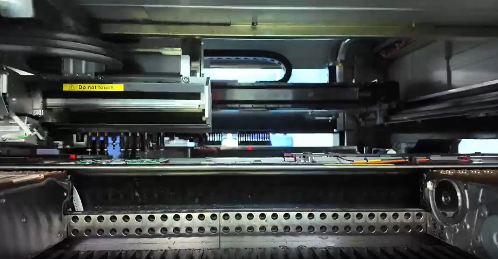
Automation in PCB Production
Automation now increases efficiency in PCB production. Automated systems improve the accuracy of layer alignment, inspection, and testing. These improvements are crucial for multi-layer stack-up manufacturing. Automation minimizes errors and maintains high-quality standards throughout the production cycle. Engineers rely on automated processes to deliver consistent results and reduce manual intervention.
Tip: Automation not only speeds up pcb production but also ensures each design meets strict quality requirements.
AI and automation together drive better signal integrity, higher efficiency, and easier compliance in modern PCB stack-up design.
Industry experts highlight several impactful trends in multi-layer PCB stack-up design for 2026.
1. High-density interconnects support miniaturization in smartphones and wearables.
2. Flexible and rigid-flex PCBs improve durability for automotive sensors.
3. Advanced materials enhance performance in high-frequency applications.
4. Sustainability drives the use of eco-friendly substrates.
5. 5G and IoT integration increases demand for optimized PCB stack-ups.
6. AI and automation boost efficiency in PCB production.
Designers can improve outcomes by following practical recommendations:
●Understand device requirements early in the design process.
●Collaborate with manufacturing teams to ensure a feasible PCB stack-up.
●Prioritize testing and validation using simulation tools.
Adaptation to new technologies and regulations remains essential. The table below shows key topics for ongoing learning:
| Key Topics | Description |
|---|
| Fundamentals of PCB Stack-Up Design | Core concepts for rigid, flex, and rigid-flex boards |
| Material selection | Choosing laminates and adhesives for each application |
| Impedance control | Achieving consistent impedance across signal layers |
| Signal integrity | Managing high-speed signals and reducing EMI |
| Thermal considerations | Addressing heat dissipation in complex PCB designs |
| Mechanical reliability | Ensuring durability in flex and rigid-flex boards |
| Manufacturability | Guidelines for cost-effective PCB fabrication |
| Layer count optimization | Balancing performance with cost constraints |
| Real-world examples | Case studies of effective stack-up design strategies |
Designers who stay informed and adapt quickly will lead innovation in pcb stack-up design.
FAQ
What is the main advantage of using HDI technology in PCB stack-up?
HDI technology allows engineers to create smaller, lighter, and more complex PCBs. Devices gain higher component density and improved electrical performance. HDI also supports faster signal transmission and better reliability in modern electronics.
How do advanced materials improve PCB stack-up performance?
Engineers select advanced materials for their low dielectric constant and high thermal conductivity. These materials reduce signal loss and manage heat more effectively. Devices achieve better speed, reliability, and longevity with the right material choices.
Why is signal integrity important in multi-layer PCB design?
Signal integrity ensures that electrical signals travel without distortion or loss. Good signal integrity prevents data errors and device malfunctions. Engineers use careful layer arrangement and impedance control to maintain strong signal quality.
What role does AI play in modern PCB stack-up design?
AI helps engineers automate stack-up planning and simulation. AI-driven tools analyze requirements, suggest optimal configurations, and predict potential issues. This technology speeds up design, reduces errors, and improves overall product quality.
As a major in Electronics and Mechanical Automation, Sonic has been engaged in PCB design, R&D, and manufacturing of electronics for around 22 years, as the engineering director, and coordinates with the supply chain(components and CNC parts), providing professional support and consulting for global customers.
 en
en


 WhatsApp