You’ll find seven major types of printed circuit boards: Single-Sided, Double-Sided, Multi-Layer, Rigid, Flexible, Rigid-Flex, and High-Frequency PCBs. These boards connect and support electronic components in almost every device you use. The global market for printed circuit boards reached $75 billion in 2021 and could grow to $120 billion by 2030. Benlida leads the way in manufacturing, offering expert solutions for all these PCB types. Your choice depends on your project needs and manufacturing options. Benlida provides professional PCB & PCBA manufacturing services for every requirement.
Key Takeaways
Printed Circuit Boards (PCBs) are essential for connecting and supporting electronic components in devices like phones and computers.
There are seven major types of PCBs: Single-Sided, Double-Sided, Multi-Layer, Rigid, Flexible, Rigid-Flex, and High-Frequency.
Single-Sided PCBs are simple and cost-effective, ideal for basic gadgets like calculators and toys.
Double-Sided PCBs allow for more complex designs by using both sides for components, making them suitable for devices like power supplies.
Multi-Layer PCBs stack multiple layers, enabling high-density circuits for advanced electronics like computers and medical devices.
Flexible PCBs can bend and twist, making them perfect for wearables and devices that need to fit into tight spaces.
Rigid-Flex PCBs combine rigid and flexible sections, offering durability and flexibility for complex designs in smartphones and aerospace.
High-Frequency PCBs are designed for fast signal transmission, essential for wireless communication and radar systems.
What Are Printed Circuit Boards
Definition
You probably see Printed Circuit Boards every day, even if you don’t realize it. These boards act as the backbone for most electronic devices. They connect and support all the tiny parts inside your phone, computer, or even your microwave. International organizations like IPC, ISO, and AS9100 set standards for how these boards are made and used. Here’s a quick look at some of those standards:
Standard
Description
IPC
Guidelines for engineers and designers, covering definitions and classifications for PCBs.
ISO 9001
Requirements for a quality management system.
AS9100
Quality management for aerospace industry.
IPC standards actually cover the entire life cycle of Printed Circuit Boards. There are over 300 IPC standards that help manufacturers create reliable and consistent boards.
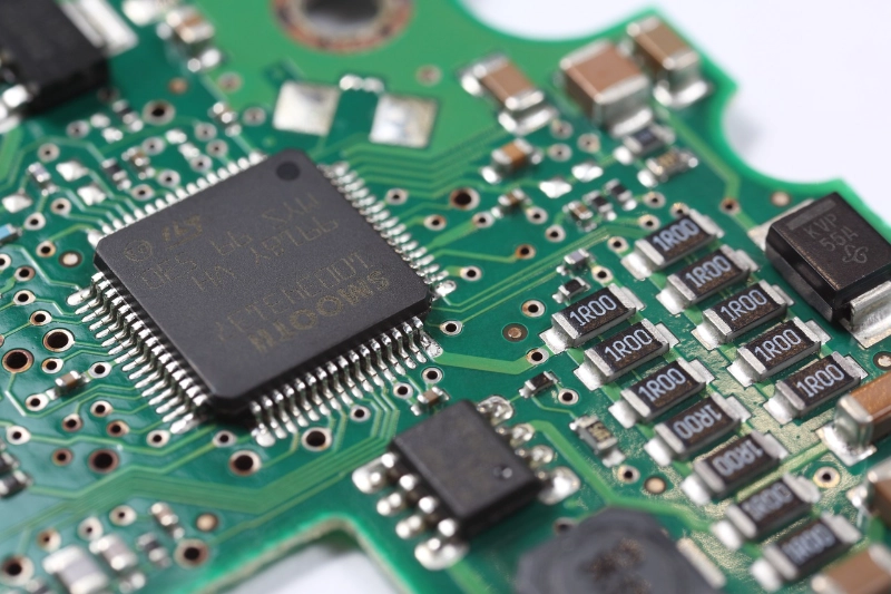
Basic Components
When you look at a PCB, you’ll notice several layers and markings. Each part has a special job. Let’s break down the main components you’ll find:
Substrate layers: This is the base, usually made from fiberglass (FR4). It gives the board strength and keeps everything insulated.
Copper traces: These thin lines act like highways, carrying electrical signals between different parts.
Solder mask: This green (sometimes other colors) layer protects the copper traces from damage and keeps them from shorting out.
Silkscreen: You’ll see letters, numbers, and symbols printed on the board. These help you place and identify components during assembly.
Tip: If you ever build or repair electronics, knowing these parts helps you troubleshoot and understand how everything works together.
Role in Electronics
Printed Circuit Boards play a huge role in making electronics reliable and efficient. You get a stable platform for mounting all your components. The copper traces ensure secure connections, so signals travel exactly where they need to go. Multi-layer boards allow for complex circuits, which means you can fit more features into smaller devices.
PCBs also make mass production possible. Manufacturers can produce thousands of identical boards, which keeps quality high and costs low. These boards withstand physical stress, so your devices last longer. You’ll find PCBs in everything from simple toys to advanced medical equipment. They drive innovation and help industries create smarter, faster, and more durable products.
The evolution from old relay circuits to modern microcontroller boards has changed how engineers design systems. Today, PCB control boards serve as the central platform for gadgets and industrial machines. Without them, modern electronics wouldn’t be possible.
Types of Printed Circuit Boards
Overview of PCB Types
You might wonder why there are so many different types of Printed Circuit Boards. Each type serves a unique purpose and fits specific needs in electronics. Here’s a quick look at the seven major types you’ll find in the industry:
Single-Sided PCBs These boards have one layer of copper. You’ll see them in simple gadgets like calculators and remote controls.
Double-Sided PCBs These use copper layers on both sides. They work well for more complex devices, such as power supplies and LED lighting.
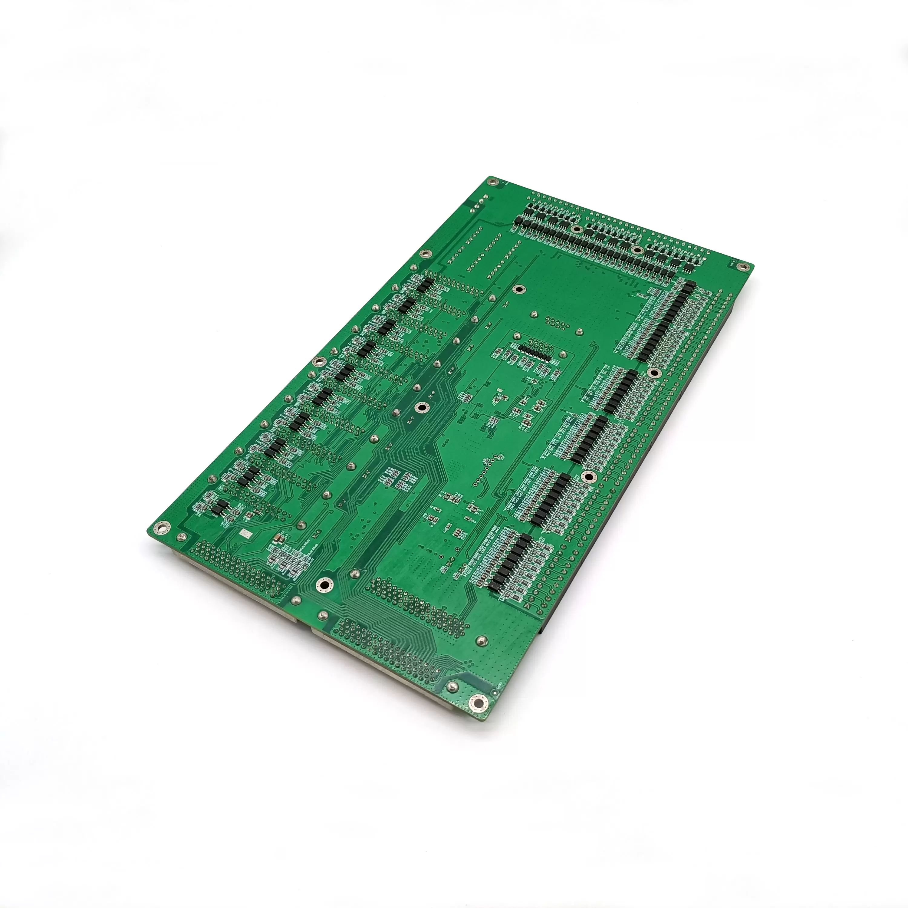
Multi-Layer PCBs These boards stack three or more layers. You’ll find them in computers, servers, and advanced medical equipment.
Rigid PCBs These boards stay firm and do not bend. They are common in desktop computers and televisions.
Flexible PCBs These can bend and twist. You’ll see them in cameras, printers, and wearable tech.
Rigid-Flex PCBs These combine rigid and flexible sections. They fit well in smartphones and military devices.
High-Frequency PCBs These handle fast signals. You’ll find them in radar systems, satellite equipment, and wireless networks.
Note: The right PCB type depends on your device’s size, function, and environment.
How Types Differ
Each PCB type stands out because of its structure, material, and the way it handles signals or stress. Some boards need to stay flat and strong, while others must bend or survive in harsh places. You might need a board that handles high power, or one that keeps signals clean and fast.
Superior thermal management, high-power density, miniaturization
Multi-layer PCB
Extreme circuit density, advanced thermal management, superior signal integrity
Rigid Flex PCB
Space and weight savings, unbreakable reliability, survives extreme environments
Ceramic PCB
Excellent thermal management, stability at high temperatures, great for high-frequency use
Flexible PCB
Lightweight, ultra-compact, adapts to tight spaces, reliable in tough conditions
HDI PCB
Miniaturization, fast signal integrity, enhanced reliability
Heavy Copper PCB
High current capacity, strong thermal management, mechanical durability
High Frequency PCB
Fast signal transmission, low signal loss, noise suppression
IC Substrate
Miniaturization, strong signal integrity, advanced thermal management
You can see that Benlida covers all the major types and even more advanced options. Whether you need a simple board for a toy or a complex one for aerospace, Benlida has the technology and experience to deliver. You get reliable products that match your project’s demands.
Tip: When you choose a PCB, think about the environment, the size of your device, and how much power or speed you need. Benlida can help you pick the best option for your application.
Single-Sided PCBs
Structure
You’ll find single-sided PCBs are the simplest type of Printed Circuit Boards. These boards have just one layer of conductive material, usually copper, placed on top of a non-conductive base. The base often uses fiberglass, which gives the board strength and insulation. On this copper layer, you’ll see all the circuit traces and pads. Components like resistors, capacitors, and chips sit on one side, while the other side stays blank.
Manufacturers add a solder mask over the copper to protect it from damage and prevent short circuits. You’ll also notice a silkscreen layer, which shows labels and symbols to help you place components in the right spots. Because everything happens on one side, the design stays straightforward. You don’t have to worry about connecting traces between layers or using special vias.
Advantages
Single-sided PCBs offer several benefits, especially if you want a simple and cost-effective solution. Here are some reasons you might choose this type:
Easy to design and manufacture: You don’t need advanced tools or complex processes. The layout stays simple, so you can finish your design quickly.
Lower production costs: Fewer materials and steps mean you save money, especially for large batches.
Reliable for basic circuits: These boards work well for low-power and low-frequency applications. You get stable performance for simple devices.
Quick turnaround time: Manufacturers can produce these boards faster, which helps if you need prototypes or small runs.
Tip: If you’re working on a project like a calculator, remote control, or basic toy, single-sided PCBs might be your best choice.
Disadvantages
Single-sided PCBs have some limitations you should consider before choosing them for your project. Here’s a table that breaks down the most common disadvantages and what they mean for your design:
Disadvantage
Explanation
Complexity limitations
You can’t fit complex circuits on a single layer. Space runs out fast, so these boards don’t work for modern electronics that need lots of connections.
Performance issues in high-speed apps
Longer signal paths can slow down transmission. This becomes a problem in high-frequency circuits, where speed and signal integrity matter.
Larger physical size
To fit all the traces, you might need a bigger board. That’s not ideal if you want to make small or compact devices.
Susceptibility to EMI
These boards are more likely to pick up electromagnetic interference. Without extra layers for grounding or shielding, sensitive applications like medical devices or RF systems may not perform well.
You’ll see these drawbacks matter most when you need advanced features, high speed, or miniaturization. For simple gadgets, though, single-sided PCBs still get the job done.
Applications
You might wonder where single-sided PCBs show up in your daily life. These boards work best in simple electronic devices. You see them in products that don’t need complex circuits or high-speed signals. Because single-sided PCBs cost less and are easy to make, manufacturers use them for mass-produced gadgets.
Here are some common applications for single-sided PCBs:
Consumer Electronics You find these boards inside calculators, remote controls, digital clocks, and basic toys. The circuits stay simple, so a single layer does the job.
Power Supplies Many low-voltage power adapters and battery chargers use single-sided PCBs. The design keeps costs down and makes assembly quick.
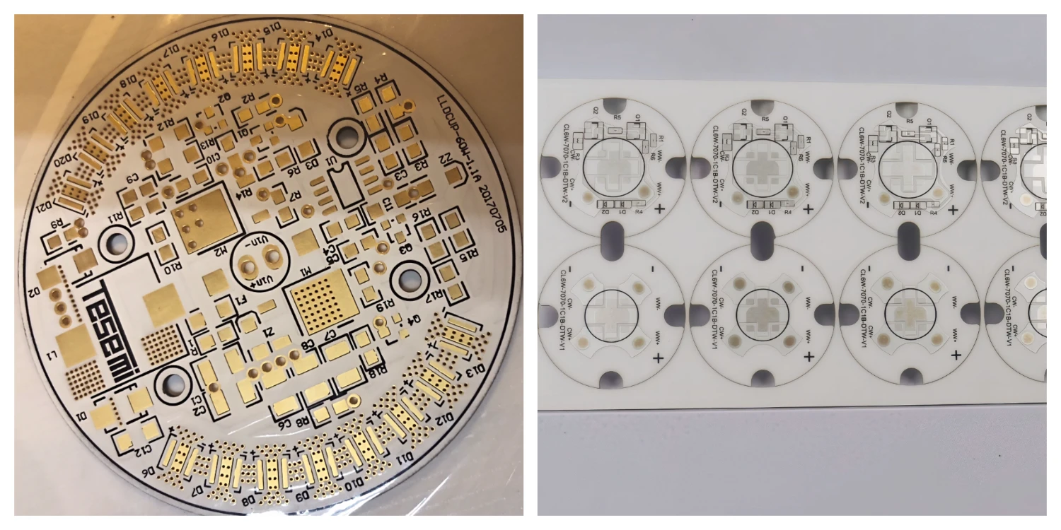
Lighting Systems LED lamps and basic lighting panels often rely on single-sided boards. You get reliable performance for simple on/off functions.
Audio Equipment Devices like radios, speakers, and amplifiers sometimes use single-sided PCBs for basic signal processing.
Home Appliances You spot these boards in kitchen timers, electric fans, and small household gadgets. The circuits don’t need much complexity.
Industrial Controls Some basic control panels and sensor modules use single-sided PCBs. These boards handle simple tasks like switching and monitoring.
Tip: If you’re designing a product that needs to be affordable and easy to assemble, single-sided PCBs might be your best choice.
Let’s look at a quick table that matches common devices with their PCB needs:
Device Type
Why Single-Sided PCB Works Well
Calculator
Simple logic, low power, low cost
Remote Control
Few components, easy layout
LED Lamp
Basic circuit, reliable operation
Kitchen Timer
Minimal features, quick production
Battery Charger
Straightforward design, cost-effective
You don’t have to worry about complex routing or high-speed signals in these devices. The single layer keeps things simple and reliable.
If you plan to build a gadget for mass production, single-sided PCBs help you save money and time. You get a board that’s easy to design, fast to manufacture, and perfect for basic electronics. Benlida can help you choose the right PCB for your project, making sure you get quality and value every time.
Double-Sided PCBs
Structure
Double-sided PCBs give you a big step up from single-sided designs. You get two layers of copper traces, one on each side of the board. This means you can place components on both sides, which helps you fit more into a smaller space. You can run traces over and under each other, so your circuit can be much more complex. Soldering happens on both sides, so you have more options for connecting parts.
Take a look at this table to see how double-sided boards compare to single-sided ones:
Feature
Double-Sided PCB
Single-Sided PCB
Layers
Two layers of conductive lines
One layer of conductive lines
Component Arrangement
Components can be arranged on both sides
All components on the same side
Complexity
Supports complex and dense designs
Limited complexity due to single layer
Soldering
Both sides can be soldered
Solder joints on one side only
Application Scope
Used for complex circuits (e.g., computers, mobile phones)
Simpler applications
You can see that double-sided boards let you build more advanced electronics. You get flexibility in design and better use of space.
Through-Hole vs. Surface Mount
When you work with double-sided PCBs, you’ll hear about two main ways to attach components: through-hole and surface mount. Through-hole technology means you push the leads of your components through tiny holes in the board and solder them on the other side. Surface mount technology lets you place components directly onto the surface, then solder them in place.
Here’s a quick table to help you compare these two methods:
Feature
Through-Hole Technology
Surface Mount Technology
Assembly Process
Components inserted into plated holes and soldered
Components soldered directly onto the PCB surface
Component Density
Lower density due to larger component footprints
Higher density with smaller components
Ease of Hand Assembly
Easier for hobbyists due to larger spacing
More challenging due to smaller pads
Prototyping
Useful for quick prototypes and proof-of-concept
More complex setup for prototypes
Cost Considerations
No need for solder stencils or pick-and-place equipment
Requires investment in automated assembly equipment
Mechanical Tolerance
More forgiving of warping and twisting during assembly
Requires high flatness for automated assembly
PCB Real Estate Utilization
Requires more space for vias and component leads
Efficient use of space with Z-axis interconnections
If you want to build a prototype or work by hand, through-hole might be easier. If you need to fit lots of parts into a small area, surface mount is the way to go. Most modern electronics use a mix of both, so you get the best of each method.
Tip: Surface mount lets you shrink your design and pack more features into your device. Through-hole gives you strength and is great for connectors or parts that need to handle stress.
Advantages
Double-sided PCBs offer you a lot of benefits. You can design more complex circuits without making the board huge. You get better performance because you can separate signal paths and reduce interference. Placing components on both sides means you use space more efficiently, which helps you make smaller devices.
Here are some reasons you might choose double-sided boards:
Higher circuit density: You can fit more connections and parts into the same area.
Flexible design options: You can route traces over and under each other, which helps with tricky layouts.
Support for advanced features: You can add more functions, like power management or signal processing.
Cost-effective for many applications: You get a good balance between complexity and price.
Wide range of uses: You’ll find double-sided boards in LED lighting, power supplies, hard drives, automotive dashboards, and consumer electronics.
Printed Circuit Boards like these help you build modern devices that need more than a simple circuit. You get reliability, flexibility, and the ability to create products that stand out.
Note: If you want to move beyond basic designs and add more features, double-sided PCBs give you the tools to do it.
Disadvantages
Double-sided PCBs give you a lot of flexibility, but you should know about a few drawbacks before you choose them for your project. These boards work well for many devices, but they do have some limits. Here’s what you need to keep in mind:
Higher Manufacturing Costs You pay more for double-sided PCBs than for single-sided ones. The extra copper layer and more complex assembly steps add to the price. If you want to keep your budget low, this might be a concern.
More Complicated Design Process You need to plan your layout carefully. Routing traces on both sides can get tricky, especially if you have lots of components. Mistakes in the design can lead to signal problems or short circuits.
Potential for Signal Interference When you pack more traces and parts onto the board, you increase the risk of electromagnetic interference (EMI). Sensitive circuits might need extra shielding or careful layout to avoid noise.
Assembly Challenges Soldering components on both sides takes more skill. Automated assembly lines handle this well, but hand-assembly can be tough. You need to watch out for alignment and solder bridges.
Testing and Repair Difficulty Troubleshooting double-sided boards can be harder. Components on both sides make it tricky to access and test each part. Repairs might take longer, especially if you need to remove parts from both surfaces.
Here’s a quick table to help you see how these disadvantages compare to single-sided PCBs:
Disadvantage
Double-Sided PCB
Single-Sided PCB
Cost
Higher
Lower
Design Complexity
More complex
Simple
EMI Risk
Increased
Lower
Assembly Difficulty
Challenging
Easy
Repair and Testing
Harder
Easier
Note: If you want to build a device with lots of features, double-sided PCBs give you the space and flexibility. You just need to plan for the extra cost and complexity.
Applications
You see double-sided PCBs in many devices around you. These boards fit well in products that need more connections and features than a single-sided board can handle. Let’s look at some common uses:
Consumer Electronics You find double-sided PCBs inside smartphones, tablets, and smartwatches. These devices need compact layouts and lots of functions.
LED Lighting Systems Modern LED panels and lighting controls use double-sided boards. You get better power management and more control options.
Industrial Equipment Machines in factories rely on double-sided PCBs for control panels, sensors, and automation systems. The extra layer helps fit complex circuits into tight spaces.
Automotive Electronics Cars use these boards for dashboards, engine controls, and entertainment systems. You get reliability and the ability to handle more features.
Medical Devices Double-sided PCBs power monitors, diagnostic tools, and portable medical equipment. You need stable performance and compact design.
Power Supplies Many power adapters and converters use double-sided boards. You get efficient layouts and improved heat management.
Here’s a table that matches devices with their PCB needs:
Device Type
Why Double-Sided PCB Works Well
Smartphone
High component density, compact design
LED Panel
Complex control, efficient power routing
Factory Sensor
Reliable connections, space-saving
Car Dashboard
Multiple functions, robust performance
Medical Monitor
Stable signals, small size
Tip: If your project needs more features, smaller size, or better performance, double-sided PCBs give you the flexibility to make it happen. Benlida can help you choose the right board and guide you through the design and manufacturing process.
Multi-Layer PCBs
Structure
When you look at multi-layer PCBs, you see a design that packs a lot of power into a small space. These boards use a “sandwich” structure. You get several layers of conductive material, usually copper, stacked with insulating layers in between. This setup lets you route signals in many directions without crowding the board. Most multi-layer PCBs include dedicated ground and power planes. These planes help keep signals clean and reduce interference.
Let’s compare the structure of different PCB types:
PCB Type
Number of Conductive Layers
Complexity Level
Double-layer
2
Limited
Multi-layer
4, 6, 8, or more
High
Multi-layer PCBs can handle intricate designs. You can fit more connections and features into a smaller area. The extra layers make these boards perfect for advanced electronics.
You’ll notice that multi-layer PCBs use at least three layers. The layers stack up with insulating material between each one. This design gives you higher circuit density and supports compact devices.
Layer Counts
You might wonder how many layers a multi-layer PCB can have. The answer depends on your project’s needs. Most boards use between 4 and 16 layers, but some go up to 60 for very complex systems.
Here’s a quick table to show you the typical range:
Layer Count Range
Common Configurations
4 to 60 layers
4 to 16 layers
More layers mean you can route signals more efficiently. You get better performance and can add more features without making the board bigger. The extra layers also help with thermal management and signal integrity.
Advantages
Multi-layer PCBs give you several benefits that make them a top choice for modern electronics. Here’s why you might pick this type:
You get increased routing density. More layers let you fit complex circuits into tight spaces.
Signal integrity improves. Dedicated ground and power planes help reduce noise and keep signals stable.
Thermal management gets better. The layered structure helps spread heat, so your devices run cooler.
You can integrate more functionality. Multi-layer PCBs let you add advanced features without making the board bulky.
You’ll find multi-layer PCBs in devices that need high performance and reliability. These boards support GPS, 5G infrastructure, networking equipment, and satellite communication systems. They play a key role in Printed Circuit Boards for telecommunications and computing.
Tip: If you want to build a device that’s small, powerful, and packed with features, multi-layer PCBs are the way to go.
Disadvantages
You might think multi-layer PCBs are the answer to every electronics problem. They pack a lot of power into a small space, but you should know about a few challenges before you choose them for your project.
First, you face higher costs. Multi-layer PCBs use more materials and need advanced manufacturing steps. You pay more for each board, especially if you need many layers or special features. If you want to keep your budget low, this can be a big factor.
Designing these boards takes skill. You need to plan every layer carefully. Routing signals between layers gets tricky. Mistakes in the design can cause problems like signal interference or short circuits. You might spend more time testing and revising your layout.
Repairing multi-layer PCBs is tough. If something goes wrong, finding the problem can be hard. Components sit close together, and traces run through many layers. You might need special tools to fix or replace parts. Sometimes, you have to replace the whole board instead of just one part.
You also face longer lead times. Manufacturing multi-layer PCBs takes more steps. You wait longer for prototypes or production runs. If you need a quick turnaround, this can slow down your project.
Here’s a table to help you see the main disadvantages:
Disadvantage
What It Means for You
Higher Cost
You pay more for materials and manufacturing
Complex Design
You need advanced skills and careful planning
Difficult Repairs
Troubleshooting and fixing take more effort
Longer Lead Times
Production and delivery take extra time
Tip: If you want to use multi-layer PCBs, work with an experienced manufacturer. They help you avoid common mistakes and keep your project on track.
You should also think about the tools and software you need. Multi-layer designs often require advanced CAD programs. You might need simulation tools to check signal integrity and thermal performance.
Multi-layer PCBs give you amazing power and flexibility, but you need to plan for these challenges. If you know what to expect, you can make smart choices and get the best results for your project.
Rigid PCBs
Structure
Rigid PCBs give you a solid, inflexible platform for mounting electronic components. You see these boards in devices that need strength and stability. The structure starts with a base layer, usually made from fiberglass-reinforced epoxy (FR4). This material keeps the board stiff and durable. On top of the base, manufacturers add copper layers. These copper traces carry signals and power between components.
You might notice other materials in the construction. Polyimide sometimes appears, especially if the board needs extra heat resistance. Stiffeners reinforce the board, making sure it doesn’t bend or flex. Adhesives like acrylic or epoxy hold everything together. Here’s a quick look at the materials you’ll find in rigid PCBs:
Material Type
Description
Polyimide
Used for heat resistance and sometimes for reinforcement.
Copper
Essential for signal and power paths; thickness varies by design.
Stiffeners
Reinforce the board; can be polyimide or FR4.
Adhesives
Acrylic, epoxy, or polyimide-based; chosen for specific needs.
You get a board that stays flat and strong, even when you mount heavy connectors or large chips. The rigid structure makes assembly easier and helps protect delicate parts.
Advantages
Rigid PCBs offer you several benefits, especially if you work in industries like automotive or aerospace. These boards resist shock and vibration, so your devices stay reliable in tough conditions. You can pack more components into a smaller space, which helps reduce the weight of your system. Rigid PCBs also support dynamic flex connections, letting the board handle bending cycles without failing.
Manufacturers like using rigid PCBs because they simplify assembly. Fewer interconnections mean faster production and fewer chances for mistakes. You also save money when you build assemblies with multiple rigid sections. Here’s a table that highlights the main advantages for automotive and aerospace applications:
Advantage
Description
High-shock and high-vibration resistance
Perfect for rugged environments and extreme conditions.
Increased package density
Lets you shrink your system and cut down on weight.
Dynamic flex connections
Handles repeated bending without breaking.
Simplified assembly
Fewer connections make production faster and more reliable.
Lower production costs
Saves money, especially with multiple rigid sections.
You get a board that’s tough, efficient, and cost-effective. Rigid PCBs help you build products that last longer and perform better.
Disadvantages
You should know about a few drawbacks before you choose rigid PCBs for your project. These boards don’t bend or flex, so they won’t fit in devices that need to twist or fold. If your design needs flexibility, you might want to look at other types of Printed Circuit Boards. Repairs can be tricky, too. Once you mount components, removing or replacing them takes extra effort. Rigid PCBs also need precise manufacturing. Any mistake in the design or assembly can lead to problems down the road.
If your device faces extreme temperature changes, you need to pick materials carefully. Some rigid boards might not handle heat as well as flexible ones. You also have to consider the size and shape. Rigid PCBs work best in devices with enough room for a flat, sturdy board.
Tip: If you want a board that stays strong and reliable, rigid PCBs are a great choice. Just make sure your device doesn’t need to bend or twist.
Applications
You see rigid PCBs everywhere, even if you don’t realize it. These boards show up in devices that need a strong, stable foundation. If you open up your desktop computer or television, you’ll spot a rigid PCB holding everything together. You get reliable performance because the board doesn’t bend or flex.
Let’s look at some places where rigid PCBs make a big difference:
Consumer Electronics You find rigid PCBs inside laptops, gaming consoles, and smart TVs. These boards keep all the chips and connectors in place. You get smooth operation and long-lasting devices.
Automotive Systems Cars rely on rigid PCBs for engine control units, dashboard displays, and entertainment systems. The boards handle vibration and heat, so your car electronics stay safe and stable.
Industrial Equipment Factories use rigid PCBs in control panels, robotics, and sensors. You get dependable performance in tough environments. The boards resist shock and keep machines running smoothly.
Medical Devices Rigid PCBs power monitors, imaging equipment, and diagnostic tools. You need accuracy and reliability in healthcare, and these boards deliver.
Aerospace and Defense Airplanes and satellites use rigid PCBs for navigation, communication, and control systems. The boards survive extreme conditions and keep critical systems working.
Home Appliances You see rigid PCBs in washing machines, refrigerators, and microwave ovens. The boards manage sensors, timers, and displays. You get convenience and durability in your kitchen.
Here’s a table that matches common devices with their PCB needs:
Device Type
Why Rigid PCB Works Well
Desktop Computer
Stable platform, supports heavy components
Car Dashboard
Handles vibration, reliable connections
Factory Robot
Tough, resists shock and heat
Medical Monitor
Accurate signals, long-term reliability
Satellite
Survives extreme environments
Washing Machine
Manages controls, stands up to wear
Tip: If you want your device to last and perform well, rigid PCBs give you the strength and stability you need.
Benlida supports all these industries with high-quality rigid PCBs. You get boards that meet strict standards and work in demanding conditions. Whether you build computers, cars, or medical equipment, Benlida helps you choose the right PCB for your project. You can count on expert advice and reliable products every time.
You might wonder how rigid PCBs help with new technology. These boards support advanced features like high-speed data, wireless communication, and smart sensors. You get the flexibility to design modern devices without worrying about board failure.
If you plan to launch a new product or upgrade an existing one, consider rigid PCBs for your design. You get a board that stands up to daily use and keeps your electronics running smoothly. Benlida’s experience and manufacturing capabilities make it easy for you to get the best results.
Flexible PCBs
Structure
You might be surprised by how different flexible PCBs look compared to the rigid boards you see in most electronics. Flexible PCBs use thin, bendable materials like polyimide dielectric film and rolled copper. These materials let you twist, fold, or shape the board to fit tight spaces or unusual designs. You can mold flexible PCBs into three-dimensional shapes, which is something rigid boards just can’t do.
Take a look at this table to see how flexible PCBs stand out from rigid types:
Feature
Flexible PCBs
Rigid PCBs
Materials
Thin substrates, polyimide film, rolled copper
Interwoven glass fiber
Flexibility
Bendable, twistable, highly flexible
Stiff, not flexible
Shape
Fits complex 3D shapes
Flat and rigid
Layer Construction
Single, double, or multi-layered
Usually multi-layered, always rigid
Dielectric Properties
Uniform thickness, better dielectric constant
Thickness may vary
You get a board that can handle movement and fit into places where a regular board would break or fail. Flexible PCBs can be single-sided, double-sided, or even multi-layered, so you have options for different designs.
Advantages
Flexible PCBs bring you a bunch of benefits, especially if you work with wearable tech or medical devices. The polyimide material is safe for skin contact, which means you don’t have to worry about allergic reactions. Devices become lighter and more portable because flexible PCBs reduce the need for bulky packaging. You can wrap them around curves or squeeze them into tiny spaces, making your gadgets more comfortable and easier to use.
Here’s why flexible PCBs are a smart choice for modern electronics:
Polyimide is FDA-approved for skin contact, so it’s safe for wearables and medical devices.
You can shrink your device size, making it more portable and user-friendly.
Flexible PCBs fit into odd shapes and tight spaces, giving you more design freedom.
They help you build lightweight products, which is great for anything you wear or carry.
Tip: If you want your device to be comfortable, safe, and easy to carry, flexible PCBs are the way to go.
Disadvantages
Flexible PCBs have some challenges you should know about before you choose them for your project. Manufacturing these boards costs more because the materials and production steps are expensive. If you bend them too much, they can break, which makes repairs tricky. You can’t use heavy components, so your design might be limited. The number of layers you can use is lower, which means you can’t build super complex circuits. Testing flexible PCBs takes longer and needs special tools, which adds to the cost.
Here’s a quick list of the most common disadvantages:
High material and production costs make flexible PCBs expensive to manufacture.
Bending can cause breakage, so repairs are more complicated.
Heavy components don’t work well with flexible PCBs.
Limited layer count restricts how complex your design can be.
Testing takes more time and needs specialized equipment, increasing overall costs.
Note: Flexible PCBs work best for lightweight, portable devices. If you need something tough or complex, you might want to look at other types of Printed Circuit Boards.
Applications
You see flexible PCBs in all sorts of devices around you. These boards make electronics lighter, smaller, and more adaptable. If you want to design something that bends, twists, or fits into a tight spot, flexible PCBs give you the freedom to get creative.
Let's look at some places where flexible PCBs really shine:
Wearable Technology You wear smartwatches, fitness trackers, and health monitors every day. Flexible PCBs let these gadgets wrap around your wrist or fit inside slim bands. The board bends with your movement, so you stay comfortable.
Medical Devices Doctors use flexible PCBs in hearing aids, pacemakers, and portable diagnostic tools. These boards fit inside tiny spaces and move with your body. Polyimide material is safe for skin contact, so you don’t have to worry about irritation.
Consumer Electronics You find flexible PCBs in smartphones, cameras, and foldable screens. The board lets manufacturers create thinner devices with more features. You get better performance in a smaller package.
Automotive Industry Cars use flexible PCBs in dashboard displays, airbag systems, and sensors. The board handles vibration and fits into curved surfaces. You get reliable electronics that work in tough conditions.
Industrial Equipment Factories rely on flexible PCBs for robotic arms, sensors, and control panels. The board bends and twists, so machines can move freely. You get better automation and fewer breakdowns.
Aerospace and Defense Airplanes and satellites need electronics that survive extreme environments. Flexible PCBs fit into tight spaces and handle temperature changes. You get dependable performance in critical systems.
Here’s a table that matches flexible PCB applications with their benefits:
Application Area
Why Flexible PCBs Work Well
Wearables
Comfort, skin safety, lightweight design
Medical Devices
Tiny size, safe materials, flexibility
Smartphones/Tablets
Thin profile, advanced features
Cars
Vibration resistance, curved surfaces
Robotics
Movement, space-saving
Satellites
Extreme temperature, compact electronics
Tip: If you want your device to stand out, flexible PCBs help you create new shapes and functions. You can design foldable phones, curved screens, or smart clothing. The possibilities keep growing as technology advances.
Benlida supports all these industries with high-quality flexible PCBs. You get boards that meet strict standards and work in demanding environments. Whether you build wearables, medical tools, or automotive systems, Benlida helps you choose the right PCB for your project. You can count on expert advice and reliable products every time.
Flexible PCBs open up new options for innovation. You can make electronics that fit your life, move with you, and last longer. If you want to push the limits of design, flexible PCBs give you the tools to do it.
Rigid-Flex PCBs
Structure
Rigid-flex PCBs combine the best features of rigid and flexible boards. You get a single unit that has both stiff and bendable sections. The rigid parts use materials like FR4, which keep everything strong and stable. The flexible sections use polyimide film, so you can twist or fold them. Manufacturers layer these materials together, connecting them with copper traces that run across both types.
You might see a rigid-flex PCB shaped like an “L” or “U.” The flexible part bends around corners or fits into tight spaces. The rigid part holds heavy components, like connectors or chips. You don’t need extra cables or connectors between sections. Everything stays connected inside the board.
Here’s a table to help you see the difference:
Feature
Rigid Section
Flex Section
Material
FR4, fiberglass
Polyimide film
Function
Holds components
Bends, twists, folds
Durability
High
Moderate
Use Case
Mounting, support
Routing, movement
You get a board that fits complex shapes and survives repeated bending. This structure helps you design smaller, lighter devices.
Advantages
Rigid-flex PCBs offer you many benefits. You can save space because the flexible sections fit into tight spots. You don’t need extra connectors, so your device becomes lighter and more reliable. The board handles vibration and movement, which makes it perfect for wearable tech or aerospace gear.
You get better signal quality, too. The copper traces run smoothly across rigid and flexible parts, so you avoid signal loss. Assembly becomes easier because you work with one board instead of several. You also reduce the risk of connection failures.
Here are some key advantages:
Space-saving design for compact devices
Fewer connectors and cables needed
Improved reliability and durability
Handles vibration and repeated movement
Easier assembly and testing
Better signal integrity
Tip: If you want your device to last longer and work in tough conditions, rigid-flex PCBs give you the edge.
Disadvantages
You should know about a few challenges before you choose rigid-flex PCBs. Manufacturing these boards costs more than standard options. You need special equipment and skilled workers. Design takes extra planning because you must balance rigid and flexible sections.
Repairs can be tricky. If something breaks, you might need to replace the whole board. Testing also takes longer, since you have to check both types of sections. You might face longer lead times, especially for custom shapes.
Here’s a quick list of disadvantages:
Higher manufacturing costs
Complex design process
Difficult repairs and replacements
Longer testing and production times
Note: Rigid-flex PCBs work best for advanced devices that need both strength and flexibility. If you want to build something simple, you might look at other Printed Circuit Boards.
Applications
You see rigid-flex PCBs in some of the coolest and most advanced devices around. These boards help you build electronics that need to bend, twist, or fit into tight spaces, but still stay strong where it counts. If you want to design something compact and reliable, rigid-flex PCBs give you the flexibility and durability you need.
Let’s look at where you might use rigid-flex PCBs:
Smartphones and Tablets You want your phone to be thin, light, and packed with features. Rigid-flex PCBs let manufacturers fit more components into smaller spaces. The flexible sections connect different parts, while the rigid areas hold chips and connectors.
Wearable Technology Smartwatches, fitness trackers, and medical wearables need to wrap around your wrist or move with your body. Rigid-flex PCBs make these devices comfortable and tough. You get gadgets that survive daily use and keep working.
Medical Devices Doctors rely on equipment that must be small, lightweight, and reliable. Rigid-flex PCBs power hearing aids, pacemakers, and portable monitors. The flexible parts fit into tiny spaces, while the rigid sections support sensitive electronics.
Aerospace and Defense Airplanes, satellites, and military gear face extreme conditions. Rigid-flex PCBs handle vibration, shock, and temperature changes. You get electronics that work in space, on the battlefield, or in the sky.
Automotive Electronics Cars use rigid-flex PCBs for dashboard displays, sensors, and control units. The boards fit into curved panels and tight spots. You get reliable performance, even when your car hits bumps or faces heat.
Industrial Equipment Robots, sensors, and control panels in factories need to move and flex. Rigid-flex PCBs help machines work smoothly and last longer. You get fewer connection failures and easier maintenance.
Here’s a table to help you match rigid-flex PCB applications with their benefits:
Application Area
Why Rigid-Flex PCBs Work Well
Smartphones/Tablets
Compact design, reliable connections
Wearables
Flexibility, comfort, durability
Medical Devices
Tiny size, safe materials, stable operation
Aerospace/Defense
Survives vibration, shock, temperature
Automotive
Fits curved spaces, resists heat and bumps
Industrial Equipment
Handles movement, reduces failures
Tip: If you want your device to stand out, rigid-flex PCBs help you create new shapes and functions. You can design foldable phones, smart clothing, or rugged equipment for harsh environments.
You don’t have to worry about loose cables or weak connections. Rigid-flex PCBs keep everything secure inside one board. You get better performance, longer life, and more design freedom. Benlida supports all these industries with high-quality rigid-flex PCBs. You can count on expert advice and reliable products for every project.
High-Frequency PCBs
Structure
You might notice that high-frequency PCBs look similar to other boards at first glance. The difference comes from the materials and design choices. Manufacturers use special substrates like PTFE (Teflon), Rogers, or ceramics. These materials help signals travel faster and stay clean. You see copper traces on the surface, but the thickness and width matter more here. Designers pay close attention to trace geometry because even small changes can affect signal speed.
You often find multiple layers in these boards. Each layer helps control signal paths and reduces interference. The solder mask protects the copper, just like on other Printed Circuit Boards. You also see precise via placements. Vias connect layers and help signals move quickly between them. Some boards use controlled impedance techniques. This means the traces have exact electrical properties to keep signals stable.
Here’s a table to show you what makes high-frequency PCBs unique:
Feature
Description
Substrate Material
PTFE, Rogers, ceramics
Trace Geometry
Precise width and spacing
Layer Count
Often multi-layered
Via Design
Controlled placement for fast signal travel
Impedance Control
Maintains signal integrity
Advantages
You get several benefits when you choose high-frequency PCBs for your project. The biggest advantage is signal speed. These boards handle signals above 1 GHz, so you can build devices that process data quickly. You also see less signal loss. The special materials keep your signals strong, even over long distances.
High-frequency PCBs help you reduce electromagnetic interference. The design keeps signals clean and prevents noise from affecting your device. You can fit more features into smaller spaces because the boards support higher circuit density. This means you can make compact devices without losing performance.
Here are some advantages you’ll notice:
Fast signal transmission for high-speed applications
Low signal loss and strong signal integrity
Reduced electromagnetic interference
Support for miniaturization and complex designs
Reliable performance in demanding environments
Tip: If you want your device to handle wireless communication, radar, or satellite signals, high-frequency PCBs give you the edge.
Disadvantages
You should know about a few challenges before you pick high-frequency PCBs. The materials cost more than standard options. You pay extra for PTFE or ceramic substrates. Manufacturing these boards takes special equipment and skilled workers. You might see longer lead times, especially for custom designs.
Designing high-frequency PCBs requires careful planning. Small mistakes in trace layout or via placement can cause signal problems. Testing and quality control take more time. You need advanced tools to check signal integrity and impedance.
Here’s a quick list of disadvantages:
Higher material and production costs
Complex design and manufacturing process
Longer lead times for custom orders
Requires advanced testing and quality control
Note: High-frequency PCBs work best for advanced electronics. If you need fast, reliable signals, these boards are worth the investment.
Applications
You might wonder where high-frequency PCBs actually show up in your daily life. These boards play a huge role in modern technology, especially when you need fast and reliable signal transmission. If you use a smartphone, watch TV, or connect to Wi-Fi, you already benefit from high-frequency PCB technology.
Here are some of the most common applications:
Wireless Communication Devices You use high-frequency PCBs in smartphones, tablets, and wireless routers. These boards help your devices send and receive signals quickly. You get faster downloads, clearer calls, and better connections.
Radar and Satellite Systems High-frequency PCBs power radar equipment in airports, weather stations, and even your car’s collision-avoidance system. Satellites use these boards to send data back to Earth. You rely on them for GPS, weather updates, and satellite TV.
Medical Equipment Hospitals use high-frequency PCBs in MRI machines, CT scanners, and wireless patient monitors. These boards keep signals clean and accurate, which helps doctors make better decisions.
Automotive Electronics Modern cars use high-frequency PCBs for advanced driver-assistance systems (ADAS), collision sensors, and vehicle-to-vehicle communication. You get safer driving and smarter vehicles.
Aerospace and Defense Airplanes, drones, and military gear need fast, reliable communication. High-frequency PCBs help these systems work in tough environments and at high speeds.
Industrial Automation Factories use high-frequency PCBs in robotics, sensors, and control systems. These boards keep machines running smoothly and help you get real-time data.
Here’s a table to help you see where high-frequency PCBs make a difference:
Application Area
Why High-Frequency PCBs Matter
Smartphones & Wi-Fi
Fast data, clear signals, reliable connection
Radar & Satellite
Accurate tracking, long-distance communication
Medical Devices
Clean signals, precise imaging
Automotive Systems
Safety features, real-time response
Aerospace & Defense
High-speed, tough environments
Industrial Automation
Real-time control, efficient operation
Tip: If your project needs to handle fast signals or work in a noisy environment, you should consider high-frequency PCBs. They help you avoid signal loss and keep your devices running at top speed.
Benlida supports all these industries with advanced high-frequency PCB manufacturing. You get boards that meet strict standards and deliver reliable performance. Whether you design wireless gadgets, medical tools, or automotive systems, Benlida helps you choose the right PCB for your needs.
You can push the limits of technology with high-frequency PCBs. They let you build smarter, faster, and more connected devices. If you want to stay ahead in your field, these boards give you the edge.
Other Notable PCB Types
You’ve already seen the seven major PCB types, but there’s even more to explore. Benlida also manufactures advanced boards that push the limits of technology. Let’s check out three standout options you might need for your next project.
HDI PCBs
HDI stands for High-Density Interconnect. You’ll find these boards in devices that need to be small but powerful. HDI PCBs use microvias, fine lines, and thin materials. This lets you pack more components into a tiny space. You see HDI boards in smartphones, tablets, and high-speed networking gear.
Why choose HDI PCBs?
You get miniaturization for sleek designs.
Signal integrity stays strong, even at high speeds.
You can add more features without making your device bulky.
Tip: If you want your gadget to be thinner and smarter, HDI PCBs make it possible.
Here’s a quick table to show where HDI PCBs shine:
Application
Benefit
Smartphones
Compact, powerful
Medical devices
Tiny, reliable
Networking gear
Fast, efficient
Ceramic PCBs
Ceramic PCBs use materials like alumina or aluminum nitride. These boards handle heat better than standard PCBs. You’ll see ceramic PCBs in high-power electronics, LED lighting, and aerospace systems. The ceramic base keeps your board stable, even when temperatures rise.
Why pick ceramic PCBs?
You get excellent thermal management.
The board resists chemicals and moisture.
Signal transmission stays clear at high frequencies.
Note: If your project faces extreme heat or needs top-notch reliability, ceramic PCBs are a smart choice.
Here’s a list of common uses:
Power amplifiers
LED modules
Satellite communication
LED/Aluminum PCBs
LED and aluminum PCBs focus on managing heat. You’ll find these boards in lighting systems, automotive headlights, and power converters. The aluminum base pulls heat away from components, so your device lasts longer and works better.
Why use LED/Aluminum PCBs?
You get superior heat dissipation.
The board supports high-power LEDs.
Your lighting stays bright and reliable.
Tip: If you want your lights to shine longer and cooler, LED/aluminum PCBs are the way to go.
Here’s a table to match applications with benefits:
Application
Why It Works Well
LED lighting
Stays cool, lasts longer
Automotive lights
Handles high power
Power converters
Reliable performance
Benlida offers all these advanced PCB types. You get expert support and high-quality boards for every challenge. If you need something special, Benlida helps you find the perfect solution.
Comparing PCB Types
Key Differences
When you look at all the different types of Printed Circuit Boards, you notice each one brings something unique to the table. Some boards stay stiff and strong, while others bend and twist. You might need a board that handles high speeds, or maybe you want something simple and affordable. Here’s a quick table to help you spot the main differences:
PCB Type
Flexibility
Layers
Cost
Best For
Single-Sided
Rigid
1
Low
Simple gadgets, toys
Double-Sided
Rigid
2
Moderate
Consumer electronics, lighting
Multi-Layer
Rigid
4+
Higher
Computers, telecom, servers
Flexible
Flexible
1-4
Higher
Wearables, medical devices
Rigid-Flex
Both
2-8
Highest
Aerospace, smartphones, defense
High-Frequency
Rigid/Flex
2+
Higher
Radar, wireless, automotive
Tip: If you want a board that fits into a tight spot or wraps around a curve, flexible or rigid-flex PCBs work best. For high-speed data, high-frequency boards are the top choice.
Choosing the Right Type
Picking the right PCB for your project can feel tricky. You want to make sure your board matches your device’s needs and your budget. Here are some key factors you should think about:
Component placement: Place your parts to keep signals clean and make assembly easy.
Signal integrity: Make sure your signals travel smoothly without interference.
Thermal management: Keep your board cool so nothing overheats.
Power distribution: Give every part steady, reliable power.
Manufacturing constraints: Check what your manufacturer can handle.
Cost: Balance what you want with what you can spend.
Electromagnetic compatibility (EMC): Avoid unwanted noise and keep your device stable.
You might want a simple board for a toy, or you could need a complex, multi-layer board for a computer. If your device bends or moves, flexible PCBs make sense. For harsh environments, rigid or rigid-flex boards offer more strength. Always talk with your manufacturer about your design and goals. They can help you choose the best option for your project.
Remember: The right PCB type helps your device last longer, work better, and stay within budget. Benlida’s team can guide you through every step, so you get the perfect board for your needs.
You’ve seen how each type of Printed Circuit Boards fits different devices and industries. If you want a simple gadget, single-sided boards work well. For advanced tech, multi-layer or high-frequency boards offer more features. Think about your project’s needs, budget, and environment before you choose. Need help? Reach out to Benlida for expert advice and reliable manufacturing. Always check quality, lead time, and production capabilities to get the best results.
FAQ
What is the most common type of PCB?
You’ll see single-sided and double-sided PCBs most often. These work well for simple and mid-level electronics. If you use a remote control or a basic toy, you’re probably using a single-sided PCB.
How do I choose the right PCB for my project?
Think about your device’s size, how many features you want, and where you’ll use it. If you need help, ask your manufacturer for advice. They can guide you to the best option.
Can flexible PCBs handle repeated bending?
Yes! Flexible PCBs can bend many times without breaking. You’ll find them in wearables and foldable gadgets. Just remember, too much force or sharp bends can still damage the board.
Are multi-layer PCBs always better than single-layer ones?
Not always. Multi-layer PCBs fit more features into small spaces. If your project is simple, a single-layer board saves money and time. Pick what matches your needs.
What materials do high-frequency PCBs use?
High-frequency PCBs use special materials like PTFE (Teflon), Rogers, or ceramics. These help signals move faster and stay clear. You’ll see these boards in radar, wireless, and satellite devices.
How fast can I get my PCBs made?
Production speed depends on your design and order size. Some manufacturers, like Benlida, can deliver in as little as five days for simple orders. Complex boards may take longer.
Can Benlida help with PCB assembly too?
Absolutely! Benlida offers both PCB manufacturing and assembly services. You can get your boards made and assembled in one place, saving you time and hassle.
What industries use rigid-flex PCBs?
You'll find rigid-flex PCBs in smartphones, medical devices, cars, and aerospace equipment. These boards work well when you need both strength and flexibility in one design.
This website uses cookies to provide you with a safer and more personal experience. By accepting, you agree to the Cookie Policy and the use of cookies for advertising and analytics purposes.
 en
en


 WhatsApp