Heavy copper PCB is an important technology in specific high-power, high-current applications, especially when relating to power supply and equipments require high-current carrying capacity.
1. What is Heavy Copper PCB?
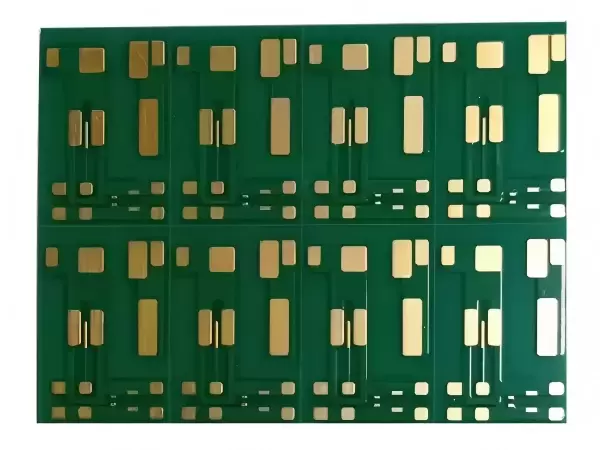
Briefly saying, heavy copper PCB is a kind of printed circuit boards which the copper foil thickness is significantly greater than conventional PCBs:
● Conventional PCBs: The outer copper layer thickness is typically 1OZ/ft² (approximately 35µm), while the inner layers are generally 0.5OZ/ft² or 1OZ/ft².
● Heavy Copper PCBs: printed circuit boards with copper thickness ≥ 3OZ/ft² (approximately 105µm) are generally defined as heavy copper PCBs. Technically, copper thickness could reach 10OZ/ft² (approximately 350µm) or even higher.
Conversion:
1OZ/ft² = 35µm (micrometers)
Common Thicknesses: 1OZ (35µm), 2OZ (70µm), 3OZ (105µm), 4OZ (140µm), 6OZ (210µm), 10OZ (350µm), etc.

2. Core Features and Advantages of Heavy Copper PCB
1) High Current Carrying Capacity: This is the primary purpose. According to the formula I = k * ΔT^0.44 * A^0.725 (IPC-2221 standard), the current carrying capacity of a conductor is positively correlated with the cross-sectional area (A) of the copper foil. Doubling the copper thickness could increase the current carrying capacity significantly, reducing the risk of overheating.
2) Excellent Heat Dissipation: Copper is good conductor, a thicker copper layer could conduct the heat more quickly which generated by components (such as MOSFET, IGBT, etc) to the heat sink or casing, reducing the operating temperature and improve reliability & lifespan.
3) Enhance Mechanical Strength: heavy copper layers provide greater mechanical strength to the connector pads and vias. This is especially beneficial for connectors which require plugging and unplugging constantly, and thicker copper provides more support to heavy components.
4) Special Designs:
● Planar Transformers/Inductors: Magnetic components could be embedded into the PCB layer directly, achieving high power density by heavy copper foils.
● Low Impedance Power Paths: Reduces voltage drop and power consumption on high-current paths.
3. Main Applications
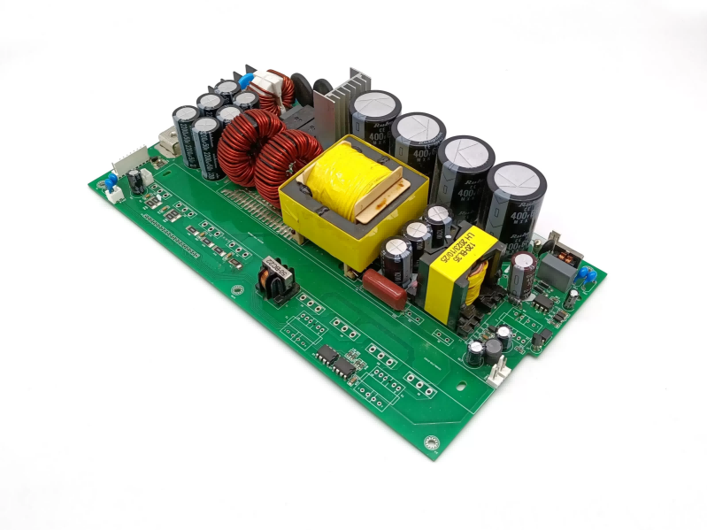
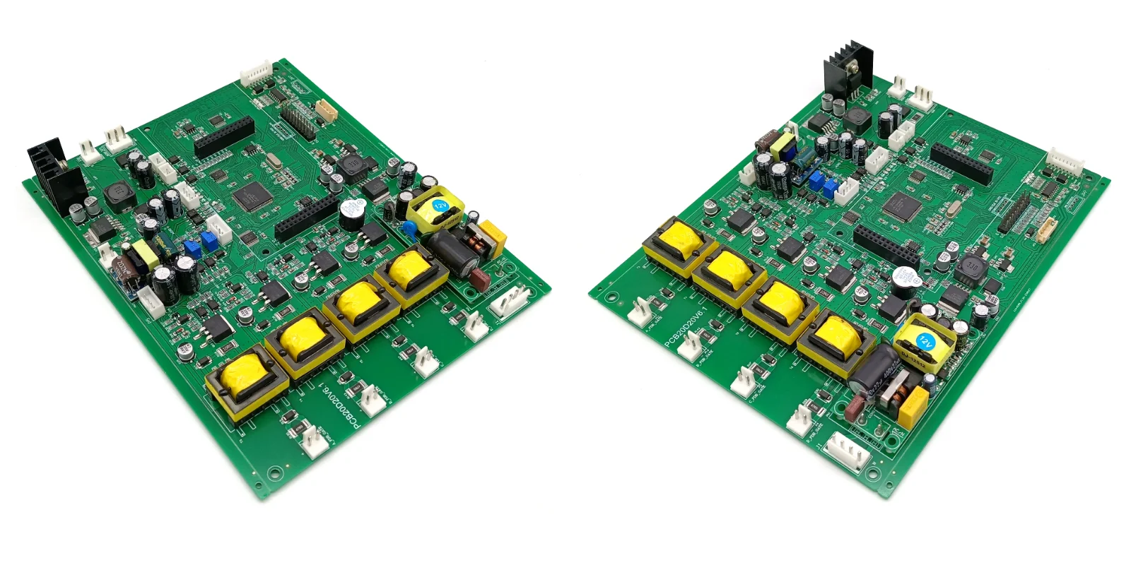
● Power Supplies: High-power AC/DC and DC/DC converters (e.g., server power supplies, industrial power supplies), UPS.
● New Energy: Solar photovoltaic inverters, wind power converters, new energy vehicles (On-Board Chargers (OBC), motor controllers, Battery Management Systems (BMS)).
● Power Control: Motor drives, industrial control, welding equipment.
● Aerospace and Military: High-reliability, high-power equipments on aviation or satelite.
● Automotives: Headlight controllers, power distribution units.
● High-Power LED Lighting: Used for heat dissipation and carrying drive current.
4. Challenges for Design and Manufacturing
Compared to traditional PCBs, heavy copper boards, while offering improved specific performance, also cause higher demands on design and manufacturing:
Challenges on Design:
● Line Width/Spacing: Etching results in "side etching," which is more severe with thicker copper. Therefore, very fine lines cannot be created. Lines on heavy copper PCBs are typically wider with larger spacing.
For example, with 3OZ copper thickness, the minimum line width/spacing may need to be 8-10 mil (0.2-0.25mm) or more.
● Copper Plating Requirements: To carry high currents and ensure mechanical strength, the copper plating on the inner walls of vias also needs to be thicker (e.g., 2-3 mil or more).
● Lamination Alignment: Due to uneven copper thickness and varying flow during lamination, alignment control is more difficult.
● Impedance Control: In high-frequency applications, thick copper affects characteristic impedance, making design calculations more complex.
Challenges on Manufacturing:
1) Pattern Transfer/Exposure: Thick copper foil makes it difficult for dry film or liquid photoresist to completely cover and form a uniform pattern, requiring high exposure uniformity.
2) Etching: One of the biggest challenges. Etching process requires more times and side etching could happen, which results in trapezoidal cross-sections instead of the ideal rectangles. It is necessary to control etching parameters and chemicals precisely.
3) Lamination: Thick copper patterns produce significant unevenness during lamination, requiring the filling of large amounts of prepreg resin. This could lead to problems such as bubbles and uneven resin flow, requires special filling and lamination processes.
4) Drilling: Thick copper layers cause rapid drill wear, potentially resulting in higher hole wall roughness. Adjustments to drilling parameters and more rigorous hole wall cleaning are required.
5) Electroplating: Ensuring a sufficiently thick copper layer is uniformly plated on the vias and surfaces, bring more challenges.
5. Key Manufacturing Processes
To encounter the challenges above, manufacturers have to consider:
● Stepped etching: Etching in multiple stages, each time etching a portion of the depth to reduce lateral etching.
● Special etching solutions: Using solutions with low lateral etching rates, such as acidic copper chloride.
● High-tonnage presses: Using high pressure to ensure the resin fully fills the gaps between the lines.
● Multiple lamination: For extremely thick copper or multi-layer thick copper boards, multiple lamination stages may be used.
● Laser ablation: For extremely high-precision thick copper patterns, direct laser forming may be used instead of traditional etching.
6. How to Distinguish "Heavy Copper PCBs" and "Copper Substrate PCBs (Metal Substrates)"
This is a common confusion:
● Heavy copper PCBs: Refers to boards with very thick copper foil on the trace layers, while the substrate remains as insulating resin material such as FR-4, CEM-3, or PI. It's primary function is to increase current carrying capacity, and secondary advantage is excellent at heat dissipation.
● Copper substrates PCBs: A type of metal substrate, it's structure is: Top layer copper foil traces → Insulating and thermally conductive dielectric layer → Overall metal substrate (usually aluminum or copper). It primarily addresses heat dissipation issues. Its copper thickness can be either the standard 1OZ or thicker copper. The core feature is a single piece of metal acting as a heatsink.
Briefly saying: a heavy copper PCB means the conductors themselves are very thick, while a copper substrate means there's a single piece of metal substrate.
Summary:
| Characteristics | Standard PCB | Heavy Copper PCB |
| Main Purpose: | Signal transportation, low-current power carrying capacity | High current carrying capacity,
efficient heat dissipation |
| Typical Copper Thickness | 1OZ (35µm) | ≥ 3OZ (105µm) |
| Line Accuracy | High, allows for fine lines | Low, requires larger line spacing |
| Cost | Relatively low | High (materials + special processes) |
| Applications | Industrial control, medical, safety, telecommunication, robotics, consumer electronics, etc. | Power supplies, new energy, industrial control, automotive power |
When choose which kind of PCB is going to apply, engineers have to evaluate current, thermal management requirements, space constraints, cost budget, and wiring density comprehensively, then to decide is heavy copper PCB the ideal option, and how thick should be the copper foils. For hihg current and heat dissipation requirements, sometimes a combination of a thick copper PCB with metal substrate could also be considered.
Benlida has been focusing on PCB manufacturing for 14 years, production experience, with mindset of market-orientation&customer-centric, we continuously upgrade manufacturing facility and optimize our production processes. If you need to produce heavy copper PCBs, please feel free to contact us!
 en
en


 WhatsApp