If you’re looking for a partner for PCB and PCBA manufacturing, reliability shouldn’t be an afterthought—it should be the core consideration from day one. Benlida supports end-to-end builds, from PCB Fabrication Service to PCB assembly, testing, and production, so reliability should be controlled across the full production progress.
1. Introduction: Why PCB Reliability Matters
Modern electronics—whether it’s a consumer device, an industrial controller, a medical monitor, or an aerospace subsystem—rarely fail “suddenly.” Most failures are the result of small weaknesses added up over time: a slightly under-plated via, a solder joint with voiding, a material choice that absorbs moisture, or a layout that concentrates heat into one corner of the board.
Reliability has real consequences:
● Safety: Automotive and medical electronics can’t tolerate intermittent faults.
● Performance: High-speed signal links degrade when impedance and stack-up drift.
● Cost: Rework, scrap, and warranty claims can quietly erase your margin.
● Brand reputation: A few field failures can damage trust for years.
This guide explains what drives PCB reliability, how PCBA quality control works in practice, and how to build for long-term PCB performance—from design, to fabrication, to assembly and testing.
2. Key Factors Influencing PCB/PCBA Reliability
Reliability is not one “feature.” It’s the outcome of correct choices across five areas:
1.materials
2.design integrity
3.assembly precision
4.protective layers and environmental resistance
5.process control and equipment capability
2.1 Material Selection
Materials define how your PCB board behaves under temperature, humidity, vibration, and time.
Substrates (laminates and cores)
● FR-4: general-purpose workhorse for many products; reliability depends heavily on Tg, resin system, and process control.
● High-Tg materials: better dimensional stability under lead-free reflow and thermal cycling.
● Polyimide: common for flexible PCBs and higher temperature tolerance when engineered correctly.
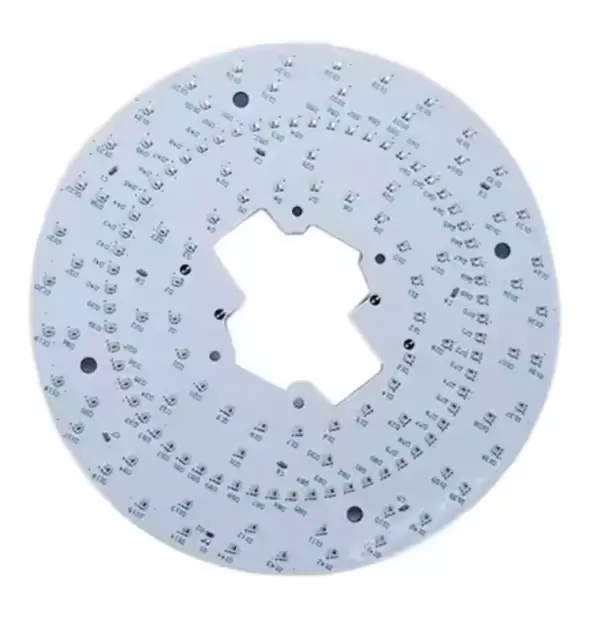
● Ceramic / metal-core (aluminum): useful for thermal performance and specific application needs (e.g., high-power LED modules).
Copper system and plating
● Copper thickness decisions influence current capacity, thermal conduction, and mechanical strength.
● Plating quality affects via fatigue life and crack resistance.
Component quality and traceability
Even with a perfect PCB, a weak component can wreck reliability. Key practices include:
● lot/date code traceability
● controlled storage for moisture-sensitive components
● incoming inspection for critical parts
● anti-counterfeit controls for hard-to-source ICs
Material-environment fit
● Humidity + contamination increase leakage risk and corrosion.
● Thermal cycling stresses plated vias and solder joints.
● Mechanical vibration stresses connectors, heavy parts, and weak pad structures.
2.2 Design Integrity
Design is where reliability is either enabled or “locked out.” A manufacturer can optimize a process, but cannot fully rescue a design that violates physics.
Trace width and copper thickness
● Under-sized traces run hot, oxidize faster, and can fail under surge load.
● Unbalanced copper distribution can cause warpage and layer stress.
Component placement and spacing
● Crowded placement increases thermal coupling and assembly defect risk.
● Poor spacing can reduce solder mask dam effectiveness and cause bridging on fine pitch.
Thermal management
Reliability often collapses from heat. Good designs control temperature by using:
● copper pours and planes for heat spreading
● thermal vias beneath hot components
● component zoning (keep hot devices away from sensitive sensors)
● smart airflow and enclosure
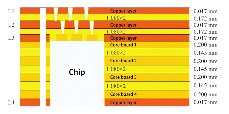
Layer stack-up and impedance control
High-speed links are sensitive to:
● dielectric thickness variation
● resin content and glass weave effects
● copper surface roughness (loss)
● reference plane continuity and return path routing
When the stack-up and impedance targets are unclear, reliability suffers as “mystery problems”: jitter, intermittent data corruption, or EMI failures that show up late.
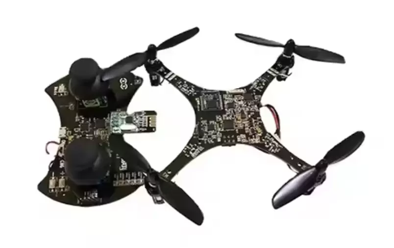
2.3 Assembly Precision
PCBA reliability is often solder-joint reliability—because the solder joint is both an electrical and mechanical interface.
Soldering techniques
● Reflow (SMT): dominant method for modern electronics; requires tight profile control.
● Wave/selective soldering (THT): used for connectors, power parts, and mechanically stressed joints.
● Selective soldering: good for mixed-technology boards when you need localized control.
Placement accuracy (SMT/THT)
Placement quality affects:
● tombstoning on passives
● skewed components (uneven wetting)
● insufficient solder fillets
● open joints on fine pitch
Solder joint quality and void control
Voids reduce thermal conduction and mechanical strength, especially in:
● power MOSFETs
● QFNs with thermal pads
● large ground pads and heat spreaders
Defect control
Common reliability-impacting defects include:
● cold joints (poor wetting)
● solder bridges (shorts)
● head-in-pillow on BGAs
● lifted pads due to thermal/mechanical stress
2.4 Protective Finishes and Environmental Resistance
Even perfect copper will degrade if it is unprotected and exposed to air and contaminants.
Solder mask quality
A solder mask is not decoration. It’s:
● insulation
● corrosion barrier
● assembly control layer
Mask adhesion, alignment, and cure quality all matter—especially for fine-pitch designs.
Surface finishes
Finish selection impacts:
● solderability window
● pad flatness
● corrosion behavior
● contact resistance (where relevant)
Common options include ENIG, HASL, and OSP, each with strengths and risks depending on your density, shelf life, and environment.
Conformal coating and encapsulation
If your product faces moisture, dust, or chemicals, coatings can dramatically improve field reliability—but they must be specified and applied correctly, or they may introduce new failures (trapped contamination, rework difficulty, poor adhesion).
Packaging and system-level protection
Board reliability is also affected by:
● moisture barrier packaging and handling
● ESD controls
● enclosure design (IP-rated seals, airflow, vibration isolation)
2.5 Manufacturing Process and Equipment
Reliability requires process repeatability. The biggest hidden killers for reliability often come from “small drift” across a production progress.
Fabrication control points
● inner layer imaging and etching accuracy
● lamination temperature/pressure uniformity
● drilling precision and registration
● desmear quality and hole wall preparation
● via plating thickness and uniformity
● final electrical test coverage
Assembly control points
● solder paste printing quality (aperture design, paste handling)
● reflow profiling, oven uniformity, atmosphere control
● AOI/X-ray inspection tuning
● rework discipline and limits
SPC and consistency
Statistical process control (SPC) helps identify drift before it becomes defects—especially for high-density boards, HDI features, or tight tolerances.
3. Testing and Quality Assurance for High Reliability
Testing verifies what you built as you needed—and that it will survive real operating conditions.
3.1 Inspection Methods
Visual inspection
Fast and useful for obvious issues, but limited by human consistency and hidden joints.
AOI (Automated Optical Inspection)
Great for:
● missing components
● polarity/orientation errors
● solder bridging
● misalignment and tombstoning
X-ray inspection
Critical for:
● BGA/LGA packages
● hidden QFN joints (especially center pads)
● internal voiding evaluation
● detecting head-in-pillow and insufficient solder under hidden joints
3.2 Functional and In-Circuit Testing
ICT (In-Circuit Test)
Typically checks:
● shorts and opens
● component presence/value (where possible)
● basic circuit integrity at node level
Best fit: stable, higher-volume programs where fixtures make sense.
FCT (Functional Circuit Test)
Validates the board in real-world-like conditions:
● power-up behavior
● communication interfaces
● sensor readings
● output performance
FCT is powerful, but often does not pinpoint the exact failing location without good test design.
3.3 Stress and Reliability Testing
Stress tests uncover “works today, fails later” issues.
● Thermal cycling: exposes expansion/contraction fatigue (vias, solder joints, laminates)
● HTOL (High Temperature Operating Life): accelerates long-term electrical/thermal stress
● Humidity testing (THB/HAST): probes moisture-driven leakage, corrosion, delamination, CAF risk
● Vibration and shock: confirms mechanical stability (connectors, heavy parts, solder fillets)
● Burn-in: screens early-life failures and marginal assemblies
3.4 Quality Standards
Standards don’t guarantee perfection, but they set discipline and traceability expectations.
Common standards and what they tend to enforce:
● ISO 9001: quality management processes and continuous improvement structure
● IPC-A-600: acceptability for bare boards (fabrication quality)
● IPC-A-610: acceptability for electronic assemblies (PCBA workmanship)
● AS9100D: aerospace-quality management requirements
● IATF 16949: automotive quality management expectations
● ISO 13485: For medical device.
● RoHS compliance: restricted substances compliance and lead-free process reality
A practical buyer approach: ask not only “do you have the certificate,” but also how the factory enforces control points, training, and management for other domains.
4. Designing for Reliability (DFM and DFT Best Practices)
Design-for-manufacture (DFM) and design-for-test (DFT) are reliability multipliers. They reduce defect opportunities and make faults easier to detect at early stage.
DFM collaboration
● clarify stack-up targets (impedance, dielectric thickness, copper)
● confirm drill sizes and aspect ratios
● define solder mask rules (dam width, expansions)
● align surface finish to component pitch and assembly method
Trace and spacing optimization
● avoid narrow neck-downs in power paths
● use consistent return paths for high-speed signals
● keep high dv/dt nodes away from sensitive nets
Component orientation and labeling
● consistent polarity marking prevents assembly mistakes
● clear reference designators support debugging and rework discipline
Thermal zoning and power distribution
● isolate heat sources
● plan copper balance to avoid warpage
● include thermal relief and heat spreading where necessary
Prioritization for critical applications
For medical, automotive, and aerospace:
● define acceptance criteria early (void targets, coating coverage, test coverage)
● require traceability and controlled process changes
● specify tighter control on via plating, lamination, and inspection
5. Evaluating PCB/PCBA Manufacturers
A reliable outcome starts with choosing a partner who can consistently reproduce your design intent.
5.1 Technology and Equipment
Look for capability alignment:
● AOI and X-ray
● stable reflow process control (profile management)
● mixed technology capability (SMT + THT)
● controlled impedance verification and documentation (when needed)
● process control checkpoints in fabrication: lamination, drilling, plating, etching, testing
5.2 Certifications and Compliance
Certifications matter most when they reflect real discipline:
● training systems
● traceability and lot control
● calibrated measurement tools
● documented process controls and corrective actions
5.3 Track Record and Service
Ask for practical methods, not marketing claims:
● first-pass yield (FPY)
● defect categories and rates (by process step)
● typical turnaround stability (on-time delivery consistency)
● how engineering change orders (ECOs) are handled
● examples of design-for-manufacture feedback that prevented issues
5.4 Supplier and Component Management
Strong procurement is a reliability tool, not just a cost tool:
● authorized sourcing strategy for key components
● substitution control and approval workflow
● counterfeit risk mitigation
● storage controls for MSD parts
● BOM planning for long-term availability
If you need a partner that can manage both fabrication and assembly with rigorous requirements, confirm they can support PCBA Manufacturing Service with traceability and test coverage that matches your application risk level.
6. Common PCB/PCBA Reliability Pitfalls
These issues show up repeatedly in field:
● Counterfeit/incorrect components: wrong suffix variants, recycled parts, or uncontrolled substitutions
● Weak solder joints: voiding, cold joints, insufficient fillets, head-in-pillow
● Thermal hotspots: designs that concentrate heat without a reliable thermal conduction path
● Via weakness: insufficient plating, poor desmear, or lamination stress leading to barrel cracks
● Environmental exposure: humidity, dust, chemicals, vibration without appropriate coating/packaging strategy
● Skipping testing: “it powers on” is not a reliability strategy
The hidden cost of unreliability is larger than scrap:
● delayed launches
● customer downtime
● warranty and recall risk
● reputation damage and lost repeat orders
7. Advanced Reliability Strategies
For demanding applications, reliability needs extra layers of control:
Material and structure upgrades
● high-Tg laminates for thermal cycling resistance
● heavy copper for power boards (when designed correctly)
● reinforced stack-ups for mechanical stability
● HDI strategies to reduce stub effects and improve high-speed behavior
Environmental protection
● conformal coating selection matched to contaminants and serviceability
● encapsulation for severe environments
● moisture control from packaging to storage to assembly
Process discipline
● SPC for critical dimensions and plating thickness
● Six Sigma mindset: reduce variation, not only defects
● preventive maintenance for drilling, imaging, plating, and reflow equipment
● controlled rework limits and documentation
Reliability becomes predictable when variation becomes predictable.
8. Applications Requiring High Reliability
Different industries fail in different ways—so reliability targets and controls should match the field reality.
● Automotive: ECUs, ADAS sensors, power modules, vibration + thermal cycling + long life
● Medical: monitoring devices, imaging systems, implant-adjacent electronics; strict traceability and workmanship requirements
● Aerospace and defense: extreme reliability expectations, harsh environments, strong verification discipline
● Industrial automation: controllers, sensors, robotics; long uptime expectations in noisy electrical environments
● Premium consumer and wearables: miniaturization pressure, high-density routing, drop/shock risk, rapid production cycles
9. Conclusion
PCB and PCBA reliability is never a single decision. It’s the combined outcome of:
● correct material selection
● reliable design rules and thermal planning
● disciplined fabrication and assembly processes
● thorough inspection and testing coverage
● strong component sourcing and traceability
The most reliable products are usually built by teams that treat reliability as a system: design + manufacturing + testing working together, early.
If you want to reduce field failures and avoid expensive rework, align reliability requirements up front and choose a partner that can control both the details and the consistency—from PCB fabrication through PCBA Manufacturing Service and verification, please feel free to contact Benlida and we’d be very happy to show we work.
About the auther:

Sonic Yang
As a major of Electronics and Mechanical Automation, Sonic has been engaged in PCB design, R&D, manufacturing of eletronics for around 22 years, as engineering director and coordinates with supply chain(components&CNC parts), providing professional supports and consults for global customers.
 en
en

 WhatsApp