As electronic devices continue to evolve toward miniaturization, flexibility, and higher circuit density, the question engineers often face is: Should I choose a flexible PCB or a rigid PCB? The answer depends on performance requirements, environmental conditions, and the physical constraints of the product itself.
Benlida Circuit, a leading manufacturer of flexible printed circuit boards (FPCs), provides both the technical insight and production capability to help designers make informed choices. Built from advanced materials such as PI, PET, and PTFE, Benlida's Flexible PCBs can endure over 100,000 flex cycles, making them ideal for compact, high-reliability electronic applications—from foldable smartphones to medical implants and automotive systems.
This article explores how flexible and rigid PCBs compare in terms of mechanical structure, electrical performance, manufacturing process, and use cases—and why flexible PCBs are becoming essential for high-density circuit applications.
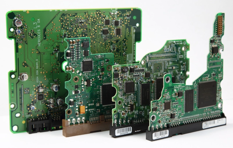
1. What Is the Core Difference Between Flexible and Rigid PCBs?
The main distinction lies in the substrate material and mechanical properties:
| Feature | Flexible PCB | Rigid PCB |
|---|
| Base Material | Polyimide (PI), PET, PTFE | FR4 (fiberglass epoxy) |
| Mechanical Property | Bendable, foldable, and shape-adaptable | Hard and fixed |
| Thickness | 0.05mm–0.3mm | 0.6mm–1.6mm |
| Copper Thickness | 0.5oz–1oz | 1oz–3oz |
| Layers | 1–12 layers | 2–16 layers |
| Surface Finish | ENIG, Immersion Silver, OSP | HASL, ENIG, OSP |
| Design Focus | Lightweight, space-saving, dynamic applications | Rigid support and thermal stability |
In essence, rigid PCBs are best for static designs where the circuit never moves, while flexible PCBs excel in environments that demand adaptability, vibration resistance, and compact architecture.
2. Why Flexibility Matters in High-Density Applications
High-density designs—such as wearable electronics, 5G modules, and advanced sensors—require tight spacing between components and efficient routing within small geometries.
Flexible PCBs solve these design challenges by:
Eliminating wiring harnesses and connectors, reducing bulk.
Allowing 3D spatial routing—circuits can fold, curve, or roll through limited spaces.
Maintaining signal integrity even in thin multilayer configurations.
Offering a lightweight solution that improves portability and mechanical efficiency.
Benlida’s 3D spatial efficiency allows engineers to fit circuits into curved dashboards, robotic joints, or implantable medical devices without redesigning the entire system architecture.
3. Electrical Performance: Stability and Signal Integrity
When it comes to signal transmission, flexible PCBs outperform traditional rigid boards in many high-speed and high-frequency environments.
Key electrical benefits include:
High-density interconnects (HDI): Line widths and spacing as fine as 0.10mm/0.10mm.
Low signal loss: Ideal for radio frequency (RF) and microwave circuits.
Reduced electromagnetic interference (EMI): Better performance for precision medical monitors and 5G antennas.
Consistent impedance control: Critical for high-frequency, low-noise signal paths.
In contrast, rigid PCBs provide excellent stability for power circuits or large components, but their planar nature can limit routing density in miniaturized systems.
4. Reliability Under Stress and Harsh Conditions
Benlida’s flexible PCBs are engineered to perform under extreme operating conditions. Their ability to bend, fold, or roll without failure makes them resilient in environments where mechanical stress or vibration would damage a rigid board.
Temperature range: -40°C to 150°C
Resistance: Moisture, dust, and vibration
Durability: Over 100,000 flex cycles without cracking or delamination
For aviation systems, automotive controls, or medical implants, reducing points of failure is essential. Flexible PCBs eliminate multiple solder joints and connectors, simplifying assembly and improving overall reliability.
Rigid PCBs, while mechanically stable, are prone to microcracking under repeated vibration or thermal cycling, especially in mobile and wearable designs.
5. Weight and Space Optimization
The ultra-thin structure of flexible PCBs—up to 70% thinner than traditional rigid boards—makes them indispensable for compact systems.
In drones, satellites, and foldable consumer electronics, every millimeter and gram counts. Flexible PCBs significantly reduce:
Device weight
Assembly height
Required internal volume
By replacing multiple rigid boards and connectors with a single flexible assembly, engineers achieve both mechanical simplicity and electrical efficiency.
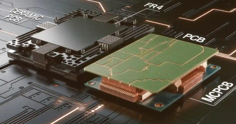
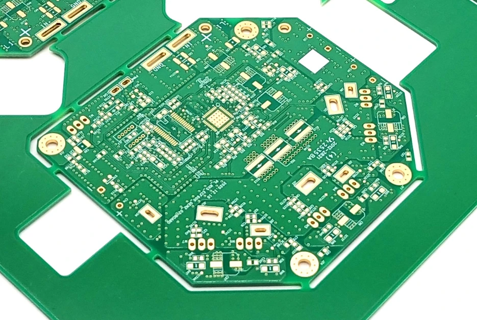
6. Manufacturing and Material Considerations
Benlida’s manufacturing capabilities allow precise customization for various performance and design needs.
Key manufacturing parameters:
Type: FPC (Flexible Printed Circuit)
Material: PI, PET, PTFE
Layers: 1–12
Copper Thickness: 0.5oz–1oz
Min. Hole Size: 0.05mm–0.1mm
Surface Finish: ENIG, Immersion Silver, OSP
Min. Trace/Space: 0.10mm / 0.10mm
Finished Thickness: 0.1mm–0.3mm
This precision ensures reliable connectivity even in high-density layouts while allowing the flexibility required by next-generation devices.
7. When to Choose Flexible PCBs Over Rigid PCBs
| Design Requirement | Recommended PCB Type |
|---|
| Constant motion or folding | Flexible PCB |
| Static, stable installation | Rigid PCB |
| Lightweight, compact product | Flexible PCB |
| Large mechanical support area | Rigid PCB |
| High-density circuit routing | Flexible PCB |
| High thermal or power load | Rigid PCB |
For most high-density and mobile electronics, the advantages of flexible PCBs are clear: smaller form factors, enhanced mechanical resilience, and superior signal performance.
However, rigid PCBs remain ideal for high-power or cost-sensitive applications, where stability and stiffness are more important than flexibility.
8. Hybrid Solutions: Rigid-Flex PCBs
In some designs, the best approach is not one or the other but a combination of both. Rigid-flex PCBs integrate rigid sections for component mounting and flexible sections for interconnection.
This structure offers:
Strong mechanical support where needed.
Reduced cabling and connectors.
Excellent reliability in complex assemblies such as cameras, automotive sensors, and medical instruments.
Benlida also supports hybrid configurations, bridging the performance gap between flexibility and strength for sophisticated designs.
9. Conclusion
As technology demands more from electronic hardware—higher speeds, smaller dimensions, and greater adaptability—the choice between flexible and rigid PCBs becomes a question of strategy rather than cost.
Flexible PCBs allow engineers to design compact, lightweight, and high-reliability systems that push beyond the limitations of traditional board layouts.
Benlida Circuit continues to lead in this transformation by delivering precision-engineered flexible PCBs built for endurance, signal integrity, and innovation. Whether for wearable technology, automotive control systems, or next-generation communications, Benlida’s manufacturing excellence ensures dependable performance where space, motion, and reliability converge.
 en
en


 WhatsApp