Beyond Tg: Understanding of PCB Material Thermal Reliability
In the design of high-speed, high-frequency and high-density electronic products, the glass transition temperature (Tg) of the PCB substrate is a well-known technical threshold. However Tg is important but it is far more than that. For reliability engineering, it requires us to establish a panoramic understanding, start with Tg, includes the relationship of thermal decomposition, dimensional stability, and electrical performance.
I. Tg: The Critical Point for Performance Changes, but not the Safety Upper Limit
Tg marks the start point of the phase transition from a rigid glassy state to an elastic rubbery state in the resin substrate. Beyond Tg, key mechanical and thermal properties will undergo non-linear degradation:
1. Dramatic Changes in Mechanical Properties: The rigidity modulus decreases significantly, weaken the PCB's resistance for bending and deformation.
2. Uncontrolled Thermal Expansion: The Z-axis thermal expansion coefficient increases dramatically by 3-5 times, generating fatal stress on metallized holes and BGA solder joints, and is the main cause of through-hole fracture and solder joint fatigue.
3. Electrical Performance Drift: The dielectric constant and loss factor begin to change significantly, affecting the integrity of high-speed signals.
Key Misconception Warning: Equate Tg value directly with the "maximum safe temperature" is dangerous. For long-term operation at temperatures which close to Tg, while not results to phase change, but indicates that the material has entered a "transition zone" of accelerated performance aging.
II. Key Partner One: Temperature of Td(Thermal Decomposition)
– The Absolute Upper Limit of Materials Thermal Decomposition temperature is a more important ultimate indicator than Tg, it marks the temperature at which irreversible chemical decomposition begins in material.
1. Relationship with Tg: Td is usually much higher than Tg (for high-performance materials, Td should be higher than 300°C). A material with high Tg but low Td may start to decompose after several times of high-temperature, lead-free reflow soldering cycles (peak temperature approximately 260°C), releases gases, lead to substrate delamination, board burst, and permanent degradation of electrical performance.
2. Engineering Significance: For products require multiple times of reflow soldering or might be operating in high-temperature environments for extended periods, Td is a more critical selection criterion than Tg. It defines the absolute boundary of a material's chemical stability.
III. Key Partner Two: CTE(Coefficient of Thermal Expansion)
– A Quantitative Standard for Stress Fields
The CTE describes the rate of dimensional change of a material when being heated. A PCB is a composite material composed of resin, glass fiber, and copper, and its CTE varies in three directions.
1. Dramatic Change at Tg Point: As mentioned earlier, the Z-axis CTE increases sharply near the Tg point.
2. Mismatch Stress: The CTE mismatch between the PCB and the components mounted on it (such as ceramic chip carriers) is the root cause of solder joint fatigue failure during thermal cycling. Therefore, it is crucial not only to consider Tg but also to pay attention to the specific values of CTE above and below Tg , so as their rate of change.
IV. The Hidden Correlation of Electrical Performance: A Core Concern for High-Speed Designers
For GHz-level high-speed circuits, the temperature-dependent curves of the material's dielectric constant and loss factor are critical.
1. Temperature Stability: Excellent high-speed boards should maintain high stability of Dk and Df across a wide temperature range, from room temperature to Tg. If the Dk value drifts excessively during heating, it will directly lead to impedance runaway and signal timing errors.
2. Comprehensive Material Selection: Therefore, high-speed designers must simultaneously consider the material's Tg, temperature stability of Dk/Df, and low-loss characteristics; all three are indispensable.
V. Engineering Strategy and How to Select Material: From Single Parameter to System Trade-offs
Application Scenarios, Core Thermal Challenges, and Priority of Key Material Parameter Selection
- Consumer Electronics: Low Cost, 2-3 times of lead-free reflows, standard Tg, acceptable of standard Td and CTE
- Automotive Electronics/Industrial Control: Long-term, high-temperature, high Tg during thermal cycling, high Td, focus on CTE matching
- Aerospace/Defense: Extreme temperature cycling, ultra-high reliability, ultra-high Tg, extremely high Td, extremely low CTE, and stable Dk/Df
- Data Center/High-Speed Communication: Signal integrity, low loss, medium-high Tg for heat dissipation, extremely stable Dk/Df, high thermal conductivity
Optimal solution for multiple parameters such as Tg, Td, CTE, and Dk/Df temperature stability in the cost, processability, and reliability triangle
Other related services regarding material Tg values:
1. Comprehensive analysis of material properties:
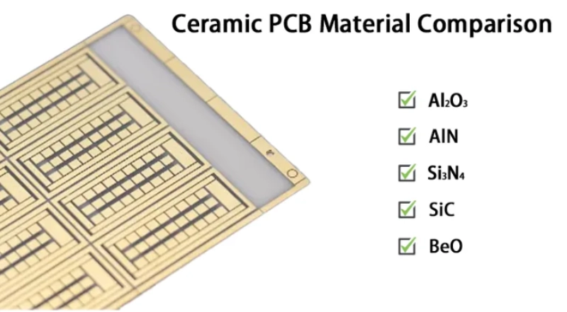
- Thermal Performance: Precisely measurement of Tg, by DSC, and Td by TGA, CTE by TMA, to create a complete thermal performance spectrum of the material from room temperature to the failure point.
- Electrical Performance: Measure Dk/Df at different temperatures using SPDR or resonant cavity methods to evaluate its temperature stability.
2. Reliability Simulation and Verification:
- Thermomechanical Simulation Support: Provides accurate material parameters for FEA simulation to predict PCB stress and deformation under thermal cycling.
- Accelerated Life Testing: Performs thermal cycling, thermal shock, and HAST tests to verify the long-term reliability of PCB assemblies.
3. Failure Analysis and Root Cause Identification: For problems such as delamination, board bursting, and solder joint cracking caused by material thermal failure, in-depth analysis is conducted using SEM/EDS, TMA, DSC, etc., to pinpoint whether the cause is improper material selection, process overheating, or design flaws.
When you encounter:
1. Confusion about PCB substrate selection for new projects
2. Signal integrity issues in high-frequency, high-speed designs
3. Unexplained product failures in high-temperature environments
4. The need to verify the authenticity of supplier material data
Benlida is dedicated to PCB manufacturing and also provides engineering services related to product reliability. With comprehensive technical and practical experience, we provide optimal service for your electronic products!
 en
en


 WhatsApp