I. Main Types of Capacitors
Classified by Dielectric Material:
1. Ceramic Capacitors
● MLCC (Multilayer Ceramic Capacitor): 0201~1210 package, 0.5pF~100μF
● High-Frequency Ceramic: NPO/C0G, good temperature stability, used in RF circuits
● High Dielectric Constant: X7R/X5R, large capacitance but average temperature characteristics
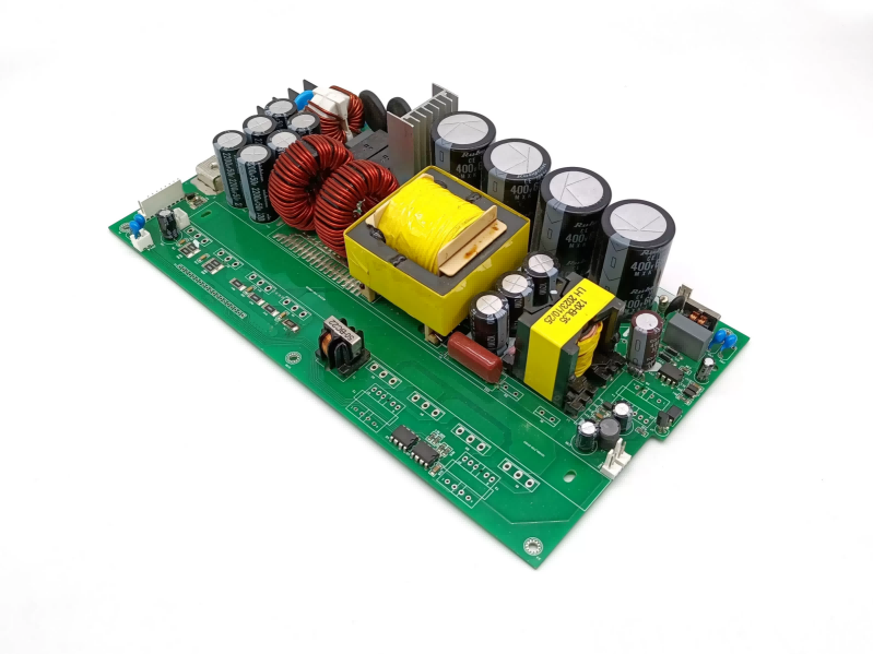
2. Electrolytic Capacitors
● Aluminum Electrolytic: Large capacitance (1μF~1F), polarized, used for power supply filtering
● Tantalum Electrolytic: Small size, low ESR, good stability, but lower withstand voltage
● Polymer Electrolytic: Ultra-low ESR, good high-frequency characteristics
3. Film Capacitors
● Polyester (Mylar): Low cost, used for general coupling
● Polypropylene (CBB): Good high-frequency characteristics, used in audio/high-frequency circuits
● Polyphenylene Sulfide (PPS): High precision, temperature stable
4. Supercapacitors
Extremely large capacity (farad level), used for energy storage and backup power.

Classified by functional and characteristics:
Decoupling capacitors: Eliminate high-frequency noise
Filtering capacitors: Smooth DC voltage
Coupling capacitors: Isolate DC and transmit AC signals
Bypass capacitors: Provide a low-frequency grounding path
Tuning capacitors: Adjust the frequency of resonant circuits
Safety capacitors: X/Y capacitors, used for EMI filtering and safety isolation
II. Functions on PCB Circuits
1. Power Management
● Buffer for Energy Storage: Provides energy reserves for instantaneous high currents
Example: Multiple MLCCs connected in parallel near the CPU to handle instantaneous load changes
● Voltage Regulation and Filtering: Eliminates power supply ripple
Switching power supply input/output terminals
LDO pre- and post-stage filtering
2. Signal Integrity
● High-frequency Decoupling: 100nF MLCCs placed near the chip's power pins
● Impedance Matching: Termination matching of high-speed signal lines
● Noise Suppression: Filters out high-frequency interference
3. Analog Circuits
● RC Filter Networks: Active/Passive Filters
● Integrator/Differentiator Circuits: Operational Amplifier Peripheral Circuits
● Sample and Hold: ADC front-end sampling capacitor
4. Timing Control
● Oscillation Timing: Crystal oscillator load capacitor (typically 10~22pF)
● Delay Circuit: RC time constant determines the delay
5. Safety and EMC
● Safety Protection: X capacitor (line-to-line), Y capacitor (line-to-ground)
● EMI Filtering: π-type/LC filter
III. Key Selection Parameters
|
Parameter |
Influence |
Typical Considerations |
|
Capacitance Accuracy |
Filter Cutoff Frequency |
Oscillation circuit requires ±1%, decoupling circuit ±20% is sufficient |
|
Voltage Rating |
Reliability |
1.5~2 times the actual voltage margin |
|
ESR |
High Frequency Performance |
Switching power supply output requires low ESR capacitors |
|
Temperature Coefficient |
Environmental Adaptability |
Automotive electronics require range -55~125℃ |
|
Dielectric Loss |
High Frequency Applications |
NPO/C0G materials for RF circuits |
IV. PCB Layout and Routing Points
1. Decoupling Capacitor Layout
● As close as possible to power pins
● Arrange from small to large (e.g., 100nF) MLCC (closest to IC, 10μF slightly further away)
2. High-Frequency Considerations
● Reduce lead inductance (use short and wide traces)
● Directly drill vias to the ground plane
3. Large Capacitor Layout
● Place large-capacity electrolytic capacitors at the power input
● Consider the impact of reflow soldering temperature on electrolytic capacitors
V. Special Application Scenarios
1. RF Circuits: High-Q NPO capacitors, precise matching
2. Power Circuits: Low-ESR polymer capacitors, withstand ripple current
3. Precision Measurement: Low leakage current, low dielectric absorption capacitors
4. High-Temperature Environments: Select X7R/X8R or higher ratings
VI. Common Problems and Solutions
Problem 1: Capacitor Whistling
Cause: Vibration caused by the piezoelectric effect of MLCCs
Solution: Use soft-terminated capacitors or replace with tantalum capacitors
Problem 2: Capacitor Failure
Preventive Measures:
● Avoid exceeding the rated voltage
● Tantalum capacitors should be derated by 50%
● Note the impact of temperature on lifespan
Problem 3: Influence of parasitic parameters
Solutions:
● Consider parasitic inductance and ESR at high frequencies
● Connect capacitors of different capacitance values in parallel at critical locations to cover the frequency band
Design Suggestions:
1. Include at least three accuracy levels when creating a capacitor library.
2. Perform SPICE simulation verification on critical circuits.
3. Consider capacitance deviations and temperature effects during production.
4. High-speed circuits require PDN (Power Distribution Network) simulation.
The correct selection and placement of capacitors directly affect circuit stability, EMC performance, and reliability, and must be comprehensively considered in conjunction with the specific application scenario.
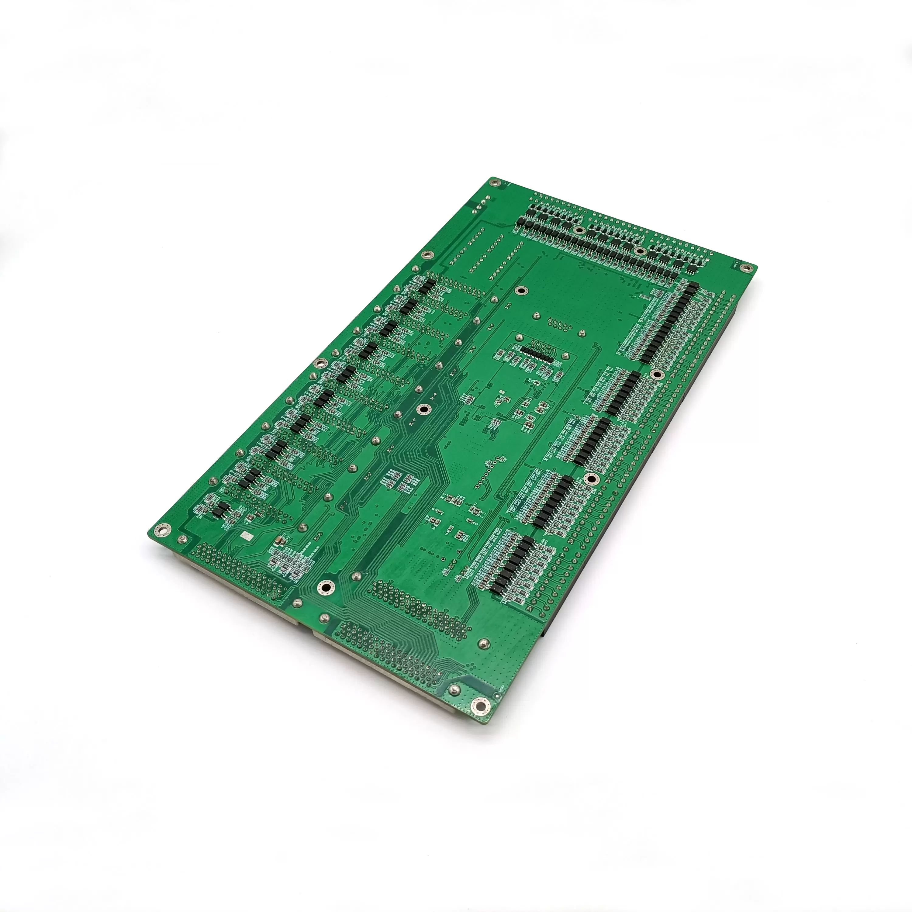
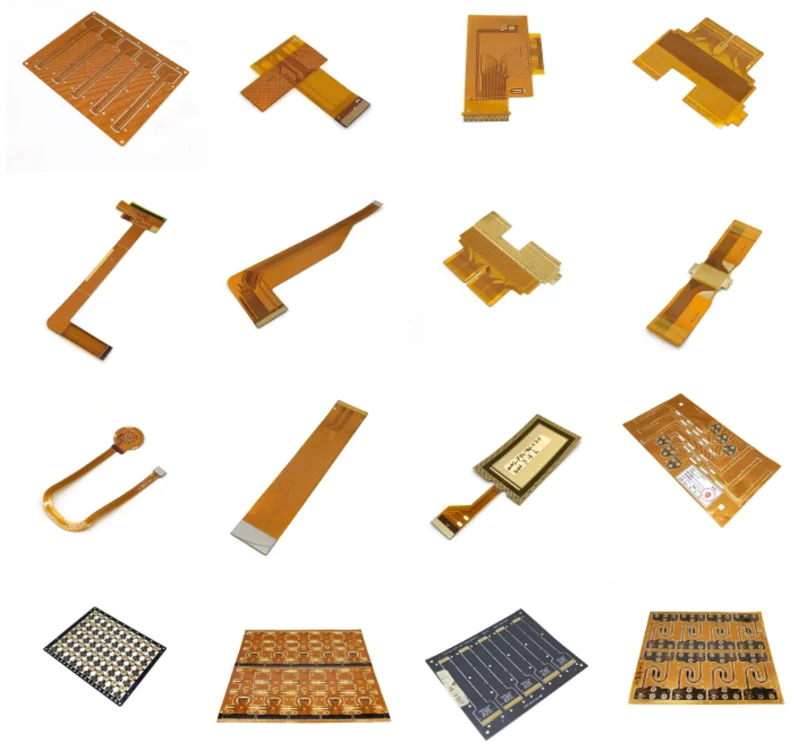
Benlida is a professional manufacturer of PCB and PCBA (PCB assembly services), with a strong supply chain, we are also committed to providing engineering services and consults to global market. If you need PCB and PCBA assembly services, please contact Benlida!
 en
en


 WhatsApp