If you’re comparing assembly methods—or troubleshooting yield issues—start with the full picture: a reliable PCB Fabrication Service sets the foundation, but the assembly process is what turns that foundation into a working product. For many OEM needs of electronics, PCB&PCBA, the fastest path to stable volume production is choosing the right assembly approach and manufactured by a capable, reliable and trustworthy partner: PCBA Manufacturing Service team that can manufacture with advanced equipment and experienced team.
1. PCB Assembly: From Bare Board to Functional Electronics
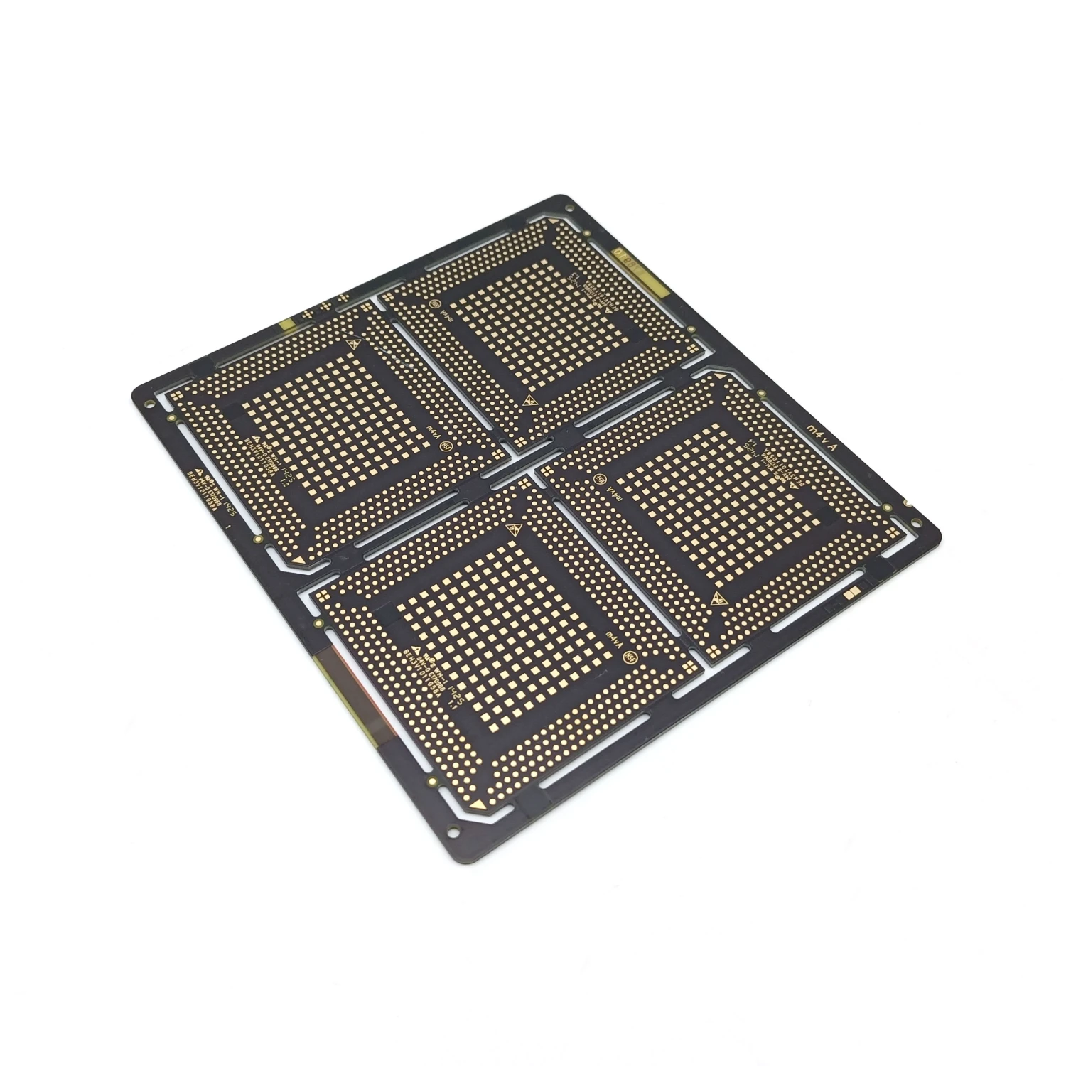
PCB Assembly (PCBA) is the process of placing and soldering electronic components onto a bare printed circuit board (PCB) so the board becomes a functional electronic. That sounds simple, but PCBA is where design intent meets the physics of soldering, heat, and manufacturing variation.
PCB Fabrication vs PCB Assembly
PCB fabrication (FAB): builds the bare board—lamination, drilling, plating, imaging/etching, solder mask, silkscreen, surface finish, and electrical test.
PCB assembly (PCBA): builds the circuit—solder paste, component placement, soldering (reflow/wave/selective), inspection, testing, and rework.
Why assembly quality impacts product performance
Even when the PCB is perfect, poor assembly can still create failures that are hard to diagnose later:
● Signal integrity: solder joint geometry, opens, micro-cracks, and via-in-pad voiding can distort high-speed edges.
● Thermal performance: voids under thermal pads, insufficient wetting, or poor copper contact increases thermal resistance.
● Reliability: warpage, brittle joints, and weak fillets lead to intermittent issues after shock or thermal cycling.
● Field failure rate: most “mystery” failures in production happen because small assembly defects scale into big reliability problems.
2. Core PCB Assembly Technologies: SMT, THT, and Mixed Assembly
Modern production of PCB assembly dominant by SMT: because it’s efficient and automotive. But THT remains essential for mechanical strength and high-power connectivity. In the real world, mixed technology is widely applied and popular—not special.
Why SMT dominates (but doesn't replace THT)
SMT is the default for ICs, passives, and high-density designs.
THT is still preferred for connectors, transformers, heavy components, and high-current paths.
Many assemblies need SMT for function and THT for durability on the same board.
Evolution: THT → SMT → Hybrid
● THT era: robust, easy to repair, large footprints.
● SMT era: miniaturization, speed, cost efficiency, high-frequency advantages.
● Hybrid era: real products combine both to meet electrical + mechanical + cost constraints.
When mixed technology is mandatory
Mixed assembly isn’t optional when you have:
● high-current connectors + fine-pitch logic
● power stages + control circuits
● Electro-mechanical interfaces + dense RF or high-speed sections
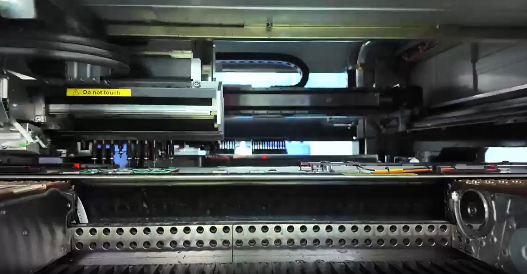
3. Surface Mount Technology (SMT): Process, Equipment & Design Rules
3.1 What is SMT?
Surface Mount Technology (SMT) mounts components directly on pads without leads which going through holes. It enables:
● high-density routing and smaller boards
● shorter interconnects (lower parasitics)
● better high-frequency behavior due to tighter loop areas
● fast automated assembly for stable volume output
3.2 SMT assembly process—step by step (technical view)
1) Stencil printing (paste volume control)
Solder paste is deposited through stencil apertures onto pads. Paste volume is the first gatekeeper of quality.
● Too much: bridging, balls, and shorts
● Too little: opens, weak joints
● Uneven deposition: unpredictable reflow behavior and rework spikes
A high-quality line often uses SPI (Solder Paste Inspection) to catch print drift before placement begins.
2) Pick & place (speed vs accuracy)
Pick-and-place machines align components using vision systems and place them onto paste.
Key drivers:
● placement accuracy (critical for QFN, BGA, fine pitch)
● CPH (components per hour) (throughput)
● vision calibration and nozzle status
● component packaging (tape/reel, trays) and feeder stability
3) Reflow soldering (thermal zones explained)
Reflow process: melts solder paste by setted heating temperature and forms joints.
Typical zone logic:
● preheat: ramps temperature smoothly to avoid thermal shock
● soak: activates flux and balances temperature across the PCB
● Reflow at peak temperature: solder melts, wets pads, forms intermetallics
● cooling: joint solidifies; cooling rate affects grain structure and brittleness
4) AOI + X-ray inspection
AOI checks visible issues: polarity, missing parts, skew, tombstoning, bridging, solder coverage.
X-ray checks hidden joints: BGA voiding, QFN center pad, head-in-pillow, internal shorts.
3.3 SMT equipment breakdown (factory-level view)
● Solder paste printer: alignment accuracy, stencil tension control, cleaning cycle discipline
● SPI: inspect the volume and coverage of solder paste on pads, remind and alert, automatively re-align and adjust the solder paste position
● Pick & place machine: gantry vs turret vs modular—each trades flexibility vs speed
● Reflow oven: hot air vs IR vs vapor phase (vapor is niche but powerful for uniform heating)
● AOI: immediate feedback loop for process tuning
● X-ray: mandatory for hidden-joint designs or high-reliability requirements
3.4 SMT advantages & limitations (engineer perspective)
SMT advantages
● high density and compact form factor
● fast automation and stable throughput
● good high-frequency performance through short interconnects
SMT limitations
● weaker mechanical anchoring than through-hole
● sensitivity to board warpage and thermal cycling
● requires tighter process control (stencil + reflow + inspection)
4. Through-Hole Technology (THT): Strength, Reliability & Use Cases
4.1 What is THT?
Through-Hole Technology (THT) inserts component leads into plated through holes (PTH) and solders them, creating strong mechanical anchoring. This is why THT survives harsh vibration environments and heavy connector stress.
4.2 THT assembly process
1.Hole drilling & plating (in FAB)
2.Insertion (manual or automated)
3.Soldering:
● wave soldering for high-throughput
● selective soldering for mixed boards or sensitive areas
4. Inspection & rework
4.3 THT equipment overview
● auto insertion: reliable for consistent pin components and high volume
● wave soldering: fast, but less selective—needs design rules and pallet strategies
● selective soldering: precise, programmable, and safer for mixed assemblies
4.4 When is THT still the best choice
● high-current connectors and power terminals
● transformers and large inductors
● industrial and automotive vibration/shock environments
● aerospace and defense designs where mechanical robustness is prioritized
5. Mixed PCB Assembly (SMT + THT): Real-World Production Standard
5.1 What is mixed technology assembly?
Mixed assembly combines SMT and THT on one PCB, often including:
Reflow soldering (thermal zones explained)
● single-sided SMT + THT
● double-sided SMT + top-side THT
● high-density SMT areas plus mechanically reinforced zones
5.2 Mixed assembly process flow (the processing order)
A common robust sequence is:
1. SMT placement + reflow (side A)
2. SMT placement + reflow (side B), if needed
3. THT insertion
4. wave or selective soldering
5. cleaning + inspection + test
Not every board uses reflows for 2 times or both sides, but sequencing always matters because each heating step affects warpage risk, component stability, and solder joint integrity.
5.3 Key challenges in mixed assembly
● thermal compatibility: SMT joints must survive later wave/selective heating
● shadowing in wave: tall SMT parts create solder wave turbulence and poor fillets
● warpage & alignment: thicker boards, uneven copper, and high-temp profiles can shift alignment
● sequencing errors: wrong order can trap flux residues, cause re-melt issues, or damage plastics/connectors
5.4 Design tips for mixed technology boards
● keep THT components away from dense fine-pitch SMT zones
● follow component height rules for wave clearance
● use solder pallets (wave fixtures) to protect SMT areas
● plan masking strategies for selective soldering, including keep-outs and access windows
● mark polarity/pin-1 clearly in silkscreen for both SMT and THT sections
5.5 Common mixed-assembly applications
● power & control boards
● automotive ECUs and gateway modules
● industrial controllers and motor drives
● medical equipment control boards
● telecom and interface cards
6. PCB Soldering Technologies: Reflow, Wave, Selective & Hand Soldering
6.1 Reflow soldering (SMT core process)
Reflow is ideal for dense SMT. The quality hinges on:
● stable paste chemistry
● correct stencil design
● a profile that balances wetting vs component stress
Lead-free vs leaded: Lead-free typically requires higher peak temperatures and tighter process stability, which makes warpage control and void reduction more important.
6.2 Wave soldering (THT workhorse)
Wave soldering is fast for through-hole but risky for mixed boards if not designed for it.
Key controls:
● flux amount and uniformity
● preheat adequacy
● wave height and contact time
● pallet design to prevent bridging and protect SMT
6.3 Selective soldering (high-end hybrid solution)
Selective soldering uses a controlled nozzle and localized heating. It’s often the cleanest choice when:
● you have mixed SMT + THT
● connectors are heat-sensitive
● you need consistent solder fillets without flooding the whole board
6.4 Hand soldering (prototypes & rework)
Manual soldering is unavoidable for prototypes, engineering changes, and rework, but it introduces variability:
● operator technique
● tip condition and temperature control
● flux management and cleaning discipline
7. PCB Assembly Defects & How to Prevent
This is where real yield gains come from: understanding mechanisms, not just defect names.
Tombstoning
● What happens: one end of a component lifts during reflow.
● Root causes: pad imbalance, paste volume asymmetry, uneven heating.
● Prevention: balanced pad design, controlled paste volume, profile tuning, and placement accuracy.
Bridging
● What happens: solder connects adjacent pads, causing shorts.
● Root causes: excess paste, tight pitch without proper stencil design, wave turbulence.
● Prevention: stencil aperture tuning, paste control (SPI), solder mask dam design, wave parameters.
Voids
● What happens: trapped gas leaves holes inside solder joints (especially QFN center pads and thermal pads).
● Root causes: flux outgassing, reflow profile issues, paste selection, surface finish interactions.
● Prevention: paste optimization, profile adjustment, thermal pad stencil design (window panes), nitrogen or vacuum solutions when required.
Cold joints
● What happens: dull, weak joints caused by poor wetting.
● Root causes: oxidation, insufficient heat, contamination, poor finish handling.
● Prevention: clean surfaces, correct profile, storage discipline, and finish selection aligned to assembly needs.
Popcorning
● What happens: moisture in components expands during reflow and cracks packaging or joints.
● Root causes: moisture exposure, incorrect bake handling, MSL violations.
● Prevention: moisture control, proper baking when required, sealed storage, and floor-life management.
Misalignment
● What happens: skewed components or off-pad placement.
● Root causes: vision calibration drift, warped boards, paste slumping.
● Prevention: equipment calibration, warpage control, stable printing, and design fiducials.
8. Single-Sided vs Double-Sided Assembly: Process & Cost Impact
● single-sided SMT: simplest, lowest risk, typically highest yield
● double-sided SMT: requires two reflow cycles; careful with heavy parts and glue strategy
● mixed single + double-sided: adds sequencing complexity and thermal management demands
Cost drivers aren’t just “more steps.” They’re also:
● additional inspection time
● higher handling risk
● more profile optimization and tighter DFM constraints
9. Turnkey vs Consignment PCB Assembly: Which Model Fits Your Project?
Choosing between turnkey and consignment isn’t just “who buys the parts”—it changes your risk, timeline control, and how problems get solved when something goes wrong.
Turnkey assembly (your partner handles BOM sourcing + assembly)
Best when you want fewer moving parts and faster coordination.
Advantages
One owner for schedule: sourcing, kitting, and assembly are synchronized, which reduces idle time on the line.
Risk reduction through alternates: experienced partners can propose approved substitutes when stock shifts—without stopping the progress.
Less procurement work: fewer supplier emails, fewer shipments, fewer packing errors, and cleaner traceability.
Better “total cost” control: fewer emergency procurement, fewer partial builds.
What to confirm up front
Approved manufacturer list (AML) / approved vendor list (AVL)
Alternate-part rules (who can approve, and what parameters must match)
Traceability level required (lot/date code/COC)
How shortages are handled (partial build vs reschedule vs substitute)
Consignment assembly (you supply parts, the factory assembles)
Best when you need control over specific parts or already have inventory.
Risks to manage
Shortages stall the whole build: one missing IC can freeze the entire schedule.
Wrong parts are common and expensive: a suffix mismatch, incorrect package, or wrong reel orientation can create a lot of rework.
Kitting overhead: labeling, MSL handling, split reels, and ESD packaging become your responsibility.
Harder root-cause ownership: if yield drops, it’s more complex to separate “part problem” vs “process problem.”
Cost structure comparison (what really changes)
Turnkey: you pay for sourcing management + potential material margin, but often save on expediting, scrap, and downtime.
Consignment: you may reduce material cost (especially if you already have stock), but you absorb hidden costs—kitting labor, shortages, repurchases, and schedule instability.
When OEMs prefer consignment
You have customer-specified components that must match exact brands/date codes.
The design includes proprietary or controlled parts (security chips, licensed modules).
You already hold inventory from long-lead purchases and want to consume existing stock.
You’re running multi-site builds and need consistent parts across factories.
10. How to Choose the Right PCB Assembly Method
Instead of choosing “SMT or THT” by habit, make the decision by constraints. Here’s a practical decision matrix you can paste into an internal SOP.
Decision matrix (fast selection)
1) Component type
Fine-pitch QFN/BGA/LGA, dense passives → SMT + reflow + AOI, often X-ray
Large connectors, transformers, high-current terminals → THT + wave/selective
Both on one board → Mixed (SMT first, then THT via selective/wave)
2) Board density
High-density routing / small board area → SMT-dominant, tighter stencil rules, higher inspection needs
Low-density, wide spacing → THT or simpler SMT is feasible
3) Operating environment
Vibration/shock, frequent plug/unplug → favor THT for mechanical anchoring
High temperature cycling → focus on joint reliability strategy (alloy, pad design, void control)
Moisture/contamination exposure → consider cleaning, coating, and inspection depth
4) Production volume
Prototype / low volume → flying probe (if needed), fixtureless test, selective solder often preferred over wave
Medium volume → SMT automation + targeted fixtures where ROI makes sense
High volume → wave/selective optimization, fixtures (ICT), line balancing becomes a major cost driver
5) Cost target
Lowest cost rarely means “fewest steps.” It means highest stable yield.
If your design forces mixed assembly, cost control comes from sequencing + DFM rather than cutting inspection.
6) Reliability class (IPC Class 1/2/3)
Class 1: consumer/low-risk—optimize for throughput and cost
Class 2: general industrial—balanced approach, stronger controls on common defects
Class 3: high-reliability—more inspection, tighter acceptance, stricter traceability and process discipline
Quick rule of thumb
If a board has fine-pitch SMT + high-current connectors, assume mixed assembly from day one and design for selective solder access. That single decision prevents most late-stage surprises.
11. PCB Assembly Equipment Line Configuration
Good PCBA is not just “having machines”—it’s configuring the line so defects could be spot out at early stage and throughput is stable.
Typical SMT line layout (high-yield setup)
Solder paste printer
SPI (catches paste drift before placement)
Pick & place
Reflow oven
AOI (first-pass defect capture)
X-ray (as required: BGA/QFN hidden joints)
Repair station + verification
Functional test (where applicable)
Why this works: the highest-leverage control point is paste volume. SPI prevents “bad print = bad day.”
Hybrid line layout (SMT + selective solder)
SMT line (printer → SPI → placement → reflow → AOI/AXI)
THT insertion (manual or automated)
Selective soldering (preferred for mixed boards) or wave soldering (if designed for it)
Cleaning (if required by flux/process/industry)
AOI/visual + X-ray checks (as needed)
Functional test / system test
Optional: burn-in / environmental screening for higher reliability builds
Bottleneck analysis (what usually limits output)
AOI/X-ray throughput mismatch: inspection becomes slower than placement/reflow.
Changeover time: feeder setup and stencil swaps can dominate short runs.
Rework loop inflation: repeated defects indicate upstream control problems (usually printing or profiling).
Selective solder cycle time: nozzle path and access constraints can cap throughput.
Line balancing & OEE optimization (practical levers)
Balance by cycle time, not machine count: one slow station sets the real capacity.
Reduce changeover through:
feeder standardization
kitting discipline
stencil management and cleaning rules
Improve OEE by tracking:
top defect Pareto + root cause (not just defect rate)
printer alignment drift, SPI trends
reflow profile stability and board warpage indicators
rework “return reasons” (why boards come back)
What signals to customers: a factory that talks about bottlenecks, feedback loops, and OEE usually has real process control—not just equipment lists.
12. Industry-Specific PCB Assembly Requirements
Automotive electronics
vibration and temperature cycling endurance
traceability and tight process controls
robust connectors and power components often require THT + selective solder
Medical devices
traceability, documentation, and repeatability
inspection depth for hidden joints
controlled change management and consistent materials
Industrial control
higher current paths and EMC considerations
stronger mechanical anchoring and stable solder joints over long duty cycles
Telecom & servers
high-speed channels, dense BGAs, strict SI needs
void control, X-ray inspection, and disciplined profile tuning
Aerospace & defense
high-reliability workmanship expectations
tighter acceptance on joints, cleaning, and traceability
process rigor matters as much as the technology choice
13. SMT vs THT vs Mixed Assembly – Technical Comparison Table
Factor | SMT | THT | Mixed |
Board density | Excellent | Limited | Excellent + robust |
Mechanical strength | Moderate | High | High where needed |
Thermal cycling tolerance | Depends on design | Strong | Strong if sequenced well |
High-frequency suitability | Excellent | Moderate | Excellent in dense zones |
Rework complexity | Medium–High | Medium | Highest |
Automation level | Highest | Medium | High, but more steps |
14. Frequently Asked Question
1.Can SMT replace THT completely?
Not for many products. If you have heavy connectors, high-current terminals, or harsh vibration, THT remains valuable.
2.Why do automotive boards still use THT?
Mechanical anchoring, connector durability, and long-term vibration resistance are the main reasons.
3.Is mixed assembly more expensive?
Usually yes, because sequencing, handling, and inspection increase—but it can reduce total cost by improving reliability and avoiding overdesign.
4.Can wave soldering damage SMT parts?
It can if parts aren’t rated, spacing is tight, or pallets/masking aren’t used properly. Selective soldering is often safer.
5.How do I design for selective soldering?
Provide nozzle access, keep-out zones, and consistent hole/pad geometry; avoid placing heat-sensitive plastics too close.
6.What IPC class should I choose?
It depends on risk tolerance and application criticality—consumer, industrial, and high-reliability products typically choose different acceptance levels.
15. How to Select a Reliable PCB Assembly Partner
When evaluating a PCBA Manufacturing Service provider, ask for proof in five areas:
Equipment capability: placement accuracy, reflow control, selective soldering capacity
Process control: SPI usage, profile management, defect feedback loops
Inspection coverage: AOI, X-ray for hidden joints, and defined rework procedures
Traceability: component lot tracking, process records, revision control
Engineering support: DFM review, alternates management, failure analysis support
The strongest partners don’t just “build to files”—they help prevent issues that don’t show up until late testing or field use.
16. Conclusion
In 2026, assembly choices are less about picking the “best” method and more about matching the method to the product:
SMT delivers density, speed, and high-frequency performance.
THT delivers mechanical strength and durability for power and connectors.
Mixed technology is often the realistic production standard for OEM boards.
If you want fewer surprises in build process, smoother ramp-up, and fewer returns later, align early on the full manufacturing chain—from PCB Fabrication Service capabilities to the right PCBA Manufacturing flow, inspection strategy, and process controls.
If you’d like, share your board type (layer count, key packages like BGA/QFN, and whether you have high-current connectors). I can help you map the most practical SMT/THT/mixed process flow and the top DFM checks to request before your next build.
About the auther:

Sonic Yang
As a major of Electronics and Mechanical Automation, Sonic has been engaged in PCB design, R&D, manufacturing of eletronics for around 22 years, as engineering director and coordinates with supply chain(components&CNC parts), providing professional supports and consults for global customers.
 en
en


 WhatsApp