Optimizing heat dissipation is key to extending the lifespan of any led pcb. Keeping the led junction temperature below 85°C can double the lifespan from 30,000 hours to over 60,000 hours. Poor thermal management often causes failures in printed circuit boards, such as excessive localized heat from clustered high-power leds, inadequate copper thickness, voids in solder joints, and restricted airflow. These issues reduce pcb reliability and performance. Proper thermal control ensures the led operates efficiently and lasts longer, making heat dissipation a critical factor in led pcb design.
Why LED Heat Dissipation Matters
Impact on LED Performance
Heat plays a major role in the operation of any led pcb. When led heat dissipation is not managed well, the led performance drops. High temperatures can cause the luminous efficacy of leds to decrease. This means the leds produce less light for the same amount of power. Color stability also suffers. As heat rises, leds may emit a warmer hue, and color output can shift. These changes affect both the look and the function of lighting systems.
●Excessive heat can cause shifts in color output.
●LEDs may emit a warmer hue as temperature rises.
●Inconsistencies can be detrimental to aesthetic and functionality.
Phosphor materials inside leds degrade faster at high temperatures. Color temperature may shift warmer or greener, and color consistency between strips can deteriorate over time. In applications where color accuracy is important, such as displays or architectural lighting, poor led heat dissipation can lead to visible flaws. Improved heat dissipation techniques help maintain led performance and extend the lifespan of the printed circuit board.
Risks of Poor Thermal Management
Ignoring thermal management for leds can cause several problems. Mechanical stress from temperature fluctuations weakens solder joints and can cause microfractures. Overheating may lead to safety concerns, including fire hazards. As heat builds up, copper resistance increases, which affects the pcb’s electrical performance. Capacitors may fail early, and thermal shutdowns can occur.
●Mechanical stress from temperature fluctuations can weaken solder joints and cause microfractures.
●Overheating can lead to safety concerns, including fire hazards.
●Increased copper resistance as temperatures rise.
●Reduced lifespan of capacitors and potential for thermal shutdowns.
Proper thermal management techniques are essential for high-power leds. They prevent damage and ensure reliable operation. Using the right techniques for led heat dissipation protects the pcb and keeps the led performance stable. Thermal management for leds is not just about efficiency; it is about safety and durability. Applying these techniques leads to improved heat dissipation and longer-lasting lighting systems.
Main Causes of Heat in LED PCBs
Electrical and Design Factors
Heat generation in a led pcb starts at the p-n junction of the led. Electrical energy converts into light and heat, but only 20-40% becomes light. The remaining 60-80% turns into heat, which accumulates at the junction. This process creates the main thermal challenge for any printed circuit board with leds. When junction temperature rises, the led lifespan drops. Every 10°C increase can halve the lifespan due to faster phosphor degradation and wire bond failure.
Design choices impact how heat moves through the pcb. Thicker copper layers, such as 2oz copper, double current capacity and improve thermal conductivity. This helps spread heat from clusters of leds, preventing droop and failures. Strategic layout can reduce junction temperatures by 20-40°C, which extends led lifespan and keeps color output stable. Smooth and clean contact surfaces are essential for effective heat conduction. Imperfect surfaces create thermal contact resistance, which blocks heat flow.
| PCB Type | Thermal Conductivity | Notes |
|---|
| MCPCB | 6-10 times that of FR4 | Superior heat transfer capabilities |
| FR-4 | Lower thermal conductivity | Can be improved with thermal vias |
Material Limitations
Material properties set the limits for thermal management in led pcb design. FR-4, a common pcb substrate, has low thermal conductivity (0.3–0.4 W/mK). This leads to poor heat transfer and heat accumulation near led junctions. Aluminum pcbs offer much higher conductivity (200–235 W/mK), which enables rapid heat transfer and reduces junction temperature. Copper provides even better heat dissipation (380–400 W/mK), making it ideal for high-power applications.
●FR-4 is not designed for high thermal loads, so heat builds up and stresses leds.
●Aluminum pcbs spread heat quickly, lowering thermal stress and improving performance.
●Using FR-4 may require oversized heat sinks and can increase failure rates during continuous operation.
Aluminum pcbs minimize hot spots and keep operating temperatures stable. This is crucial for maintaining led performance and extending the lifespan of the pcb.
Choosing LED PCB Materials
Metal-Core vs. FR4
Selecting the right substrate for a led pcb is essential for effective heat management. Metal-core materials, such as aluminum and copper, offer much higher thermal conductivity than standard FR-4. This property allows them to move heat away from the led junction more efficiently. In applications like cob lighting, where multiple leds are packed closely together, rapid heat transfer is critical.
| Material | Thermal Conductivity (W/m·K) |
|---|
| FR-4 (std) | 0.25–0.4 |
| Aluminum MCPCB | 1.0–4.0 |
| High-Tg MCPCB | 6.0–8.0 |
| Copper MCPCB | 3.0–6.0 |
Standard FR-4 has a thermal conductivity of about 0.3–0.4 W/m·K. Aluminum MCPCB ranges from 1.0 to 4.0 W/m·K, while copper MCPCB can reach up to 6.0 W/m·K. High-Tg MCPCB provides even greater values. For cob modules, using metal-core substrates helps prevent overheating and supports longer led life.
Importance of Low Thermal Resistance
Low thermal resistance in pcb materials is vital for maintaining optimal led performance. When the substrate has low resistance, heat moves quickly from the led junction to the environment. This keeps the junction temperature stable, which is crucial for light output, color accuracy, and lifespan. In cob designs, where many leds operate together, low thermal resistance prevents hot spots and ensures even heat dissipation.
| Key Point | Explanation |
|---|
| Thermal Resistance | Low resistance allows better heat transfer from the led junction outward. |
| Impact on Performance | Stable temperatures protect light output, color, and component lifespan. |
| Material Selection | Metal-core pcbs outperform FR-4 in high-power cob and led applications. |
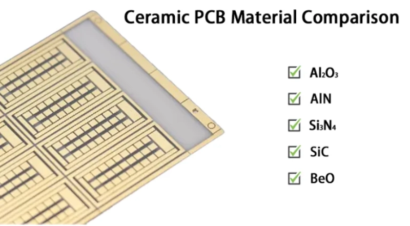
The thermal properties of the substrate, including conductivity and thickness, directly affect the reliability of cob and led systems. Standard FR-4 often cannot handle the demands of high-power cob modules, making metal-core or ceramic substrates a better choice for effective heat dissipation.
Optimizing PCB Thickness and Copper Traces
Selecting Proper Thickness
Choosing the right thickness for a pcb is essential for effective heat dissipation in led applications. Thicker copper layers, such as 2oz copper, improve thermal performance by reducing resistance and spreading heat more efficiently. This is especially important for high-power led systems, like 50-watt floodlights, where power density is high. Using 2oz copper allows for better heat distribution and enables the use of narrower traces without creating hotspots. When led arrays exceed 2 watts per chip or when currents go beyond the limits of 1oz copper, 2oz copper pcbs are recommended. This is critical in environments with limited airflow, such as automotive or industrial lighting, where thermal management is a priority.
| Copper Thickness | Typical Application | Thermal Benefit |
|---|
| 1oz | Low-power led lighting | Basic heat control |
| 2oz | High-power led floodlights | Enhanced heat transfer |
Copper Trace Width and Heat Flow
The width and thickness of copper traces play a major role in pcb thermal design. Wider traces create a low impedance path for current, which reduces resistance and limits heat generation. Copper acts as a primary heat spreader due to its high thermal conductivity. The weight of copper influences how heat spreads laterally across the pcb, preventing hotspots that can damage led performance. Narrow traces or insufficient thickness can worsen thermal issues, especially in components that dissipate high power. This leads to uneven temperature distribution and can cause leds to overheat.
Copper traces help distribute heat from concentrated led hotspots across the pcb. Maintaining a temperature below 85°C is crucial for extending led lifespan. Proper trace design ensures that heat moves away from the led junction quickly, supporting reliable operation and consistent light output.
Using Heat Sinks and Thermal Vias
Types of Heat Sinks for LED PCBs
Heat sinks play a vital role in managing heat for any led pcb. The heatsink absorbs heat from the led and pcb, then releases it into the surrounding air. Aluminum is the most common material for heatsinks because it combines high thermal conductivity with low cost. Aluminum alloy offers a conductivity of about 190 W/mK, which helps maximize heat transfer between the pcb and the heatsink surface.
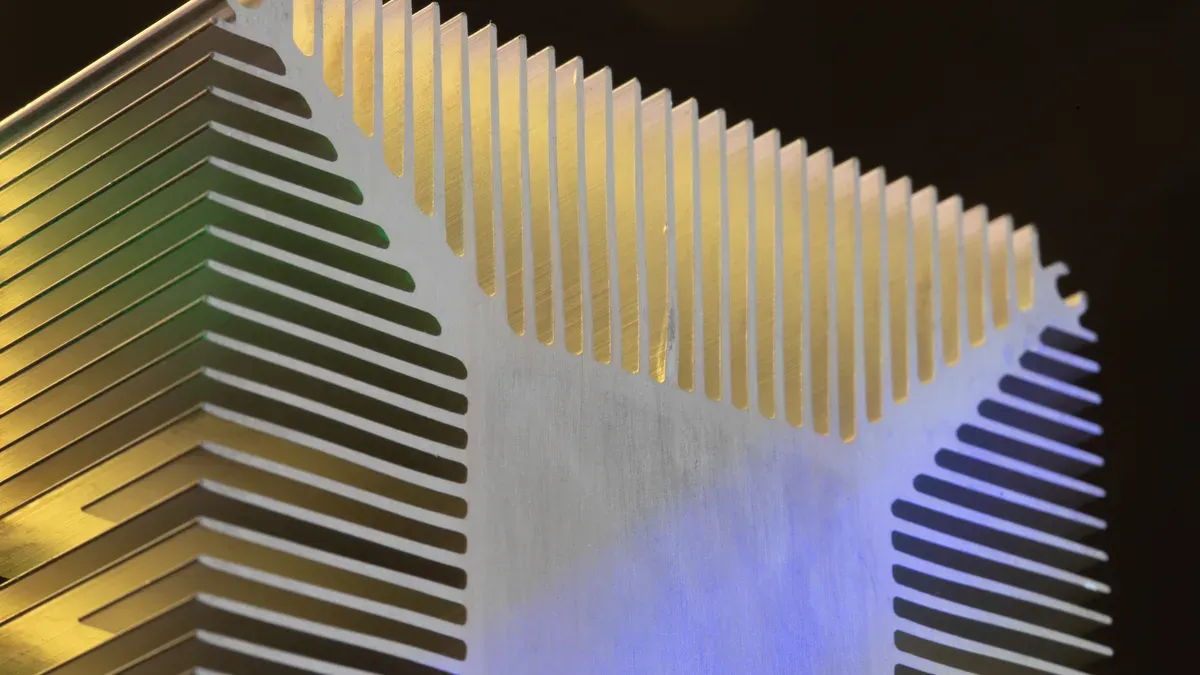
The geometry of the heatsink matters. Designers often choose shapes that increase surface area, such as fins or pins. These shapes allow more air to flow around the heatsink, improving heat dissipation. Copper and ceramic heatsinks are also used in some applications. Copper provides even higher conductivity, while ceramics offer electrical insulation along with thermal performance.
Mounting the heatsink directly to the pcb ensures efficient heat transfer. Proper alignment with thermal vias creates a direct path for heat to move from the led junction to the heatsink. This approach balances size, weight, and thermal performance. For high-power led systems, designers sometimes embed heat pipes or vapor chambers in the base of the heatsink. These additions spread heat quickly but increase cost and weight.
Heat sink design must consider the total heat generated by the led array. Larger heatsinks or thicker bases help manage higher thermal loads. In summary, the best heatsinks for led pcb assemblies use materials like aluminum, maximize surface area, and align with thermal vias for optimal heat dissipation.
Enhancing Heat Transfer with Vias
Thermal vias improve heat transfer in multi-layer pcb designs. These vias act as vertical channels that carry heat from the led junction through the pcb layers. Instead of spreading heat across the surface, thermal vias allow heat to move straight down, reducing localized temperature peaks.
The effectiveness of thermal vias depends on several factors. The number of vias, their diameter, and their connection to larger copper areas all influence thermal conductivity. Designers often place an array of vias beneath the led to create a direct path for heat. This arrangement lowers the junction temperature and extends the lifespan of the led.
| Aspect | Recommendation |
|---|
| Arrangement | Array beneath the LED |
| Diameter | 0.3-0.5 mm |
| Copper Layer Thickness | 1-2 oz per square foot |
| Number of Vias | 8-16 for high-power applications |
| Spacing | 1-1.5 mm between vias |
| Pattern | Grid (e.g., 3x3 or 4x4) |
Design considerations for thermal vias must include the placement and spacing of each via. A grid pattern beneath the led ensures even heat distribution. The diameter of each via should be between 0.3 and 0.5 mm. For high-power led applications, using 8 to 16 vias spaced 1 to 1.5 mm apart is recommended. Connecting vias to thicker copper layers increases the overall thermal conductivity of the pcb.
Thermal vias are essential for effective heat management in led pcb assemblies. They provide a direct path for heat dissipation, reduce temperature spikes, and support reliable led operation. By following these design considerations for thermal vias, engineers can extend the lifespan of the led and improve the performance of the pcb.
Maximizing Surface Area and Layout
Strategic Component Placement
Designers can improve heat dissipation in led systems by maximizing the surface area of the pcb. Increasing the copper foil area reduces thermal resistance, which helps move heat away from the led junction. However, enlarging the copper area too much may increase the distance from the heat source, lowering conduction efficiency. Careful planning is needed to balance surface area and proximity.
Strategic placement of components is essential for effective thermal management. High-power leds should be distributed evenly across the pcb. This prevents localized heat buildup and supports uniform cooling. Orienting components to expose more surface area to airflow also improves heat dissipation. Thermal vias placed in arrays beneath led pads transfer heat to inner layers or the opposite side of the pcb. Plated or filled vias prevent solder wicking during assembly.
| Best Practice | Description |
|---|
| Thermal Vias | Arrays beneath led pads transfer heat efficiently. |
| Even Distribution | Spread high-power leds evenly for uniform cooling. |
| Component Orientation | Maximize surface area exposure to airflow. |
●Maintain clearances around vias and pads for inspection.
●Place drivers and resistors downstream of leds to use pre-heated air.
●Simulate airflow with board geometry to refine component orientation.
Avoiding Thermal Hotspots
Thermal hotspots can damage leds and reduce pcb reliability. These hotspots often result from poor heat dissipation paths or inadequate via placement. Engineers use thermal imaging to identify hotspots and adjust layouts. Adding thermal vias or changing component placement can enhance heat dissipation.
Effective layout strategies include using thicker copper, with 2oz recommended for power densities above 3 W/cm². Optimal thermal via design features diameters of 0.3–0.4 mm and densities of 8–12 vias per cm² under high-power leds. Minimum spacing of 3–5 mm between same-bin leds prevents thermal coupling. Staggered array patterns help reduce hotspots. Multi-layer pcb designs with solid copper heat sink interfaces improve thermal management. Maintaining a copper-free border of more than 5 mm avoids thermal shadowing.
| Strategy | Description |
|---|
| Copper Thickness | Thicker copper lowers thermal resistance. |
| Thermal Via Design | Proper via size and density under leds. |
| LED Placement | Adequate spacing and staggered arrays. |
| Multi-layer Design | Solid copper heat sink interface. |
| Edge Effects | Copper-free border prevents shadowing. |
●Incorporate thermal vias beneath led pads.
●Orient components for maximum airflow.
●Place drivers downstream of leds.
Cooling Solutions for LED PCBs
Effective cooling is essential for maintaining the performance and lifespan of any led system. Engineers use a range of led cooling techniques to manage heat and prevent damage. Both passive and active cooling methods play important roles in mastering thermal management for leds. The right choice depends on the application, the amount of heat generated, and the design constraints of the pcb.
Fans and Heat Pipes
Active cooling methods, such as fans and heat pipes, provide powerful solutions for high-power led applications. Fans move air across the surface of the pcb, increasing the rate of heat transfer. This approach works well in environments where leds generate significant heat, such as industrial lighting or outdoor displays. Fans can quickly lower the temperature of the led junction, which helps maintain stable light output and color.
Heat pipes offer another advanced led cooling technique. These devices use a sealed tube filled with a working fluid. When heat from the led warms one end of the pipe, the fluid evaporates and moves to the cooler end, where it condenses and releases heat. This process creates a rapid and efficient transfer of heat away from the led. Heat pipes are lightweight and silent, making them suitable for compact or noise-sensitive applications.
| Cooling Method | Application Area | Advantages |
|---|
| Fans | High-power leds, large arrays | Fast heat removal, adjustable |
| Heat Pipes | Compact, silent systems | Efficient, no moving parts |
Active cooling increases system complexity and cost. It also requires regular maintenance, especially for fans. However, these methods are essential for mastering thermal management for leds in demanding environments.
Thermal Compounds and Interface Materials
Thermal interface materials play a critical role in led cooling techniques. These materials fill microscopic gaps between surfaces, such as between a led and a heatsink. Without a proper interface, air pockets can form, which act as insulators and trap heat. A good thermal interface material ensures efficient heat transfer by creating a continuous path for heat to flow from the led to the cooling solution.
Common types of thermal interface materials include thermal pastes, pads, and adhesives. Each type offers different levels of performance and ease of application. Metal-core pcbs, which often serve as the base for high-power leds, exhibit thermal conductivity values ranging from 1 to 4 W/m-K. This property enhances heat management capabilities and supports reliable operation.
●Thermal interface materials with higher conductivity improve overall cooling efficiency.
●Proper application of interface materials reduces thermal resistance and prevents overheating.
●Interface pads are easy to install and provide consistent performance in mass production.
Thermal compounds, such as silicone-based pastes, are often used in led assemblies. These compounds spread easily and fill tiny voids, ensuring maximum contact between the led and the heatsink. Pads and adhesives offer a cleaner alternative, especially in automated assembly lines.
Passive cooling methods, such as metal-based heatsinks and copper traces, remain popular for many led applications. These systems are affordable and reliable. Passive cooling does not consume additional energy, making it a silent and efficient choice for devices that do not generate excessive heat. Household electronics and standard led lights often use passive cooling because it meets their thermal needs without added complexity.
●Passive cooling is best for low-to-moderate heat loads.
●It provides silent operation and long-term reliability.
●Active cooling becomes necessary when heat output exceeds the capacity of passive systems.
Selecting the right combination of cooling methods and interface materials ensures that the pcb operates within safe temperature limits. This approach extends the lifespan of the led and maintains consistent performance.
Application & Environment Considerations
Indoor vs. Outdoor LED Use
The environment where a led operates has a strong impact on its heat dissipation and thermal management. Indoor and outdoor settings present different challenges for keeping the led cool and reliable.
●High ambient temperatures outdoors can cause the pcb to overheat. This may break circuit traces and weaken the structure of the board.
●Limited airflow, both indoors and outdoors, can trap heat around the led and heat sink. This makes it harder for the system to cool down.
●The installation surface matters. If the led is mounted on a surface that does not support good thermal transfer, heat can build up and reduce efficiency.
●Outdoor leds often face higher temperatures and more direct sunlight. This increases the need for strong thermal solutions to keep the led junction temperature low.
●Poor airflow or improper installation can lead to higher internal temperatures, which lowers the reliability of the led.
Managing Humidity and Temperature
Humidity and temperature changes can affect the thermal performance and lifespan of a led system. Moisture in the air can cause several problems for the pcb and its components.
| Impact Type | Description |
|---|
| PCB moisture and short circuits | Moisture can create conductive paths on PCBs, leading to leakage and power failures. |
| LED encapsulation degradation | High humidity can cause resin hydrolysis, reducing luminous efficiency and lifespan. |
| Corrosion of metal components | Prolonged humidity can rust screws and connectors, reducing conductivity and causing failures. |
| Surface condensation | Dew formation from temperature fluctuations can blur images, requiring manual cleaning. |
Temperature swings can also stress the led and its thermal system. Rapid changes may cause condensation, which leads to corrosion or short circuits. High humidity can damage the encapsulation of the led, lowering its light output and shortening its life. Corrosion from moisture can affect connectors and screws, making the thermal path less effective.
To protect leds, use sealed enclosures for outdoor installations. Choose materials that resist corrosion and support good heat transfer. Monitor both humidity and temperature to maintain stable thermal conditions and extend the lifespan of the led system.
Signs of Inadequate LED Thermal Management
Common Overheating Symptoms
Detecting problems with thermal management in led systems is important for preventing failures. Overheating often shows clear signs on the pcb. Hotspots that measure more than 20°C above the average surface temperature signal a serious issue. These hotspots usually form near the led junction, where most heat gathers. Rapid color shift is another warning sign. When the led changes color quickly, it means the junction temperature is rising too high. This can affect both the brightness and the quality of the light.
●Hotspots greater than 20°C above average
●Rapid color shift
●Dimming or flickering leds
●Burn marks near the led junction
●Unusual smells from overheated components
Infrared thermal imaging helps engineers find these problems early. This technology creates a real-time map of the pcb’s surface temperature. It can spot overheating at the led junction without touching the board. High-resolution thermal cameras make it possible to see even small temperature changes. This method is essential for keeping the led junction temperature within safe limits and ensuring reliable operation.
Recommended Thermal Thresholds
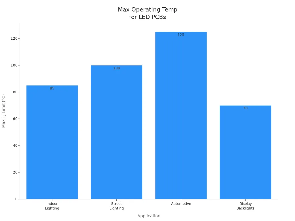
Maintaining the correct junction temperature is key to long-lasting led performance. Each application has its own maximum safe junction temperature. Indoor lighting should keep the junction below 85°C. Street lighting can allow up to 100°C at the junction. Automotive systems have a higher limit, with the junction reaching 125°C. Display backlights need the lowest junction temperature, usually not exceeding 70°C.
| Application | Typical Tj Limit |
|---|
| Indoor Lighting | 85°C |
| Street Lighting | 100°C |
| Automotive | 125°C |
| Display Backlights | 70°C |
The ambient temperature also affects how much current the led can handle. At temperatures below 25°C, the led can run at 100% of its rated current. Between 25°C and 40°C, the current should drop to 85-90%. For 40°C to 60°C, reduce the current to 70-80%. If the temperature goes above 60°C, lower the current to 60-70% or improve the thermal design. Keeping the junction temperature under control prevents heat damage and extends the life of the led.
Effective heat dissipation strategies for led PCBs include using metal-core materials, optimizing component placement, and applying thermal interface materials. Regular monitoring helps maintain led performance and prevents overheating, which extends lifespan. Industry standards like JEDEC guide thermal management and material selection. Improved techniques, such as thermal via arrays and copper plane layers, support enhanced led lifespan. Adapting cooling solutions and airflow design ensures reliable operation across different environments.
| Technique | Benefit |
|---|
| Thermal Via Arrays | Reduce hotspots in led PCBs |
| Copper Plane Layers | Lower junction temperatures |
| Conductive Epoxy | Boost heat dissipation |
About the author:

Sonic Yang
As a major in Electronics and Mechanical Automation, Sonic has been engaged in PCB design, R&D, and manufacturing of electronics for around 22 years, as the engineering director, and coordinates with the supply chain(components and CNC parts), providing professional support and consulting for global customers.

 en
en



 WhatsApp