Impedance, commonly represented by symbol Z, measured in ohms (Ω), influence a circuit's opposition to the current flow. It consists by two parts: resistance and reactance, expressed by the formula Z=R+jX. Here, R is the resistance, which always impedes the current flow; X is the reactance, caused by inductance (inductive reactance) and capacitance (capacitive reactance), and it introduces a phase difference between current and voltage.
The fundamental purpose of impedance matching in circuits is to ensure that energy (or signal) can be efficiently transferred, without distortion from the source to the load.
I. Maximum Power Transfer
This is the most classic theory, especially crucial in radio frequency and power amplifier circuits.
Maximum Power Transfer Theorem
When the load impedance ZL equals the complex conjugation of the source impedance ZS (for a purely resistive circuit, simply equal RL=RS), the load obtains maximum power from the source.
If the load impedance is too high, the voltage is high but the current is low; If the load impedance is too low, the current is high but the voltage is low. Only with impedance matching, the voltage and current (power) could reach its maximum value.
Application Scenarios:
RF Circuits: Antennas and receivers/transmitters must be matched. Otherwise, a large amount of signal will be reflected back, resulting in ineffective radiation or reception.
Audio Amplifiers: The amplifier's output impedance needs to be matched with the speaker impedance, to achieve the loudest volume and highest efficiency.
II. Eliminating Signal Reflections and Ensuring Signal Integrity
This is the most common and critical reason in high-speed digital circuit design.
Signal Reflection
When a signal propagates in a transmission line (such as PCB traces, cables), if the characteristic impedance of the transmission line does not match the load impedance, some energy will be reflected back by the load, just like light reflecting off a mirror.
Serious Consequences
Ringing: The reflected wave superimposes with the subsequent signal, causing the signal waveform to oscillate.
Overshoot/Undershoot: The signal level exceeds or falls below the expected value.
Timing Errors: Ringing and distortion would cause clock or data signals to be at incorrect times, resulting in system errors and crashes.
Application Scenarios
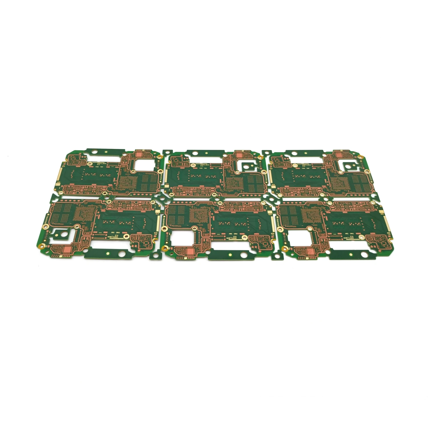
High-speed digital products, such as DDR memory, PCIe, USB, and HDMI, which require impedance control (typically 50Ω, 90Ω, or 100Ω differential) and terminating resistors (e.g., series or parallel terminations) at the ends to eliminate reflections.
III. Reducing Signal Distortion Primarily for analog signals, especially high-frequency signals.
Frequency Response
Circuit impedance typically varies with frequency. If impedance mismatch occurs, signal components at different frequencies will experience different transmission efficiencies and phase changes.
Consequences
This leads to distortion in the amplitude-frequency characteristics (different gains at different frequencies) and phase-frequency characteristics (different delays at different frequencies) of the output signal, i.e., linear distortion.
Application Scenarios
Measurement Instruments: Oscilloscopes and spectrum analyzers, typically have input ports designed to be 50Ω or 1MΩ, requiring probe matching with the circuit under test to ensure the accuracy of the measured waveform.
Analog Video Transmission: Impedance mismatch can cause image ghosting and color distortion.
When can impedance matching be ignored?
When the length of the transmission line is much shorter than the signal wavelength (i.e., low-frequency circuits), the signal propagation time on the wire is extremely short, and reflection is not significant. In this case, impedance matching can be temporarily disregarded. This is why simple Arduino or 51 microcontroller development boards could function normally in low-speed digital circuits (such as LEDs and buttons) without matching. However, once the signal rate reaches the MHz or GHz level, matching becomes essential and critical.
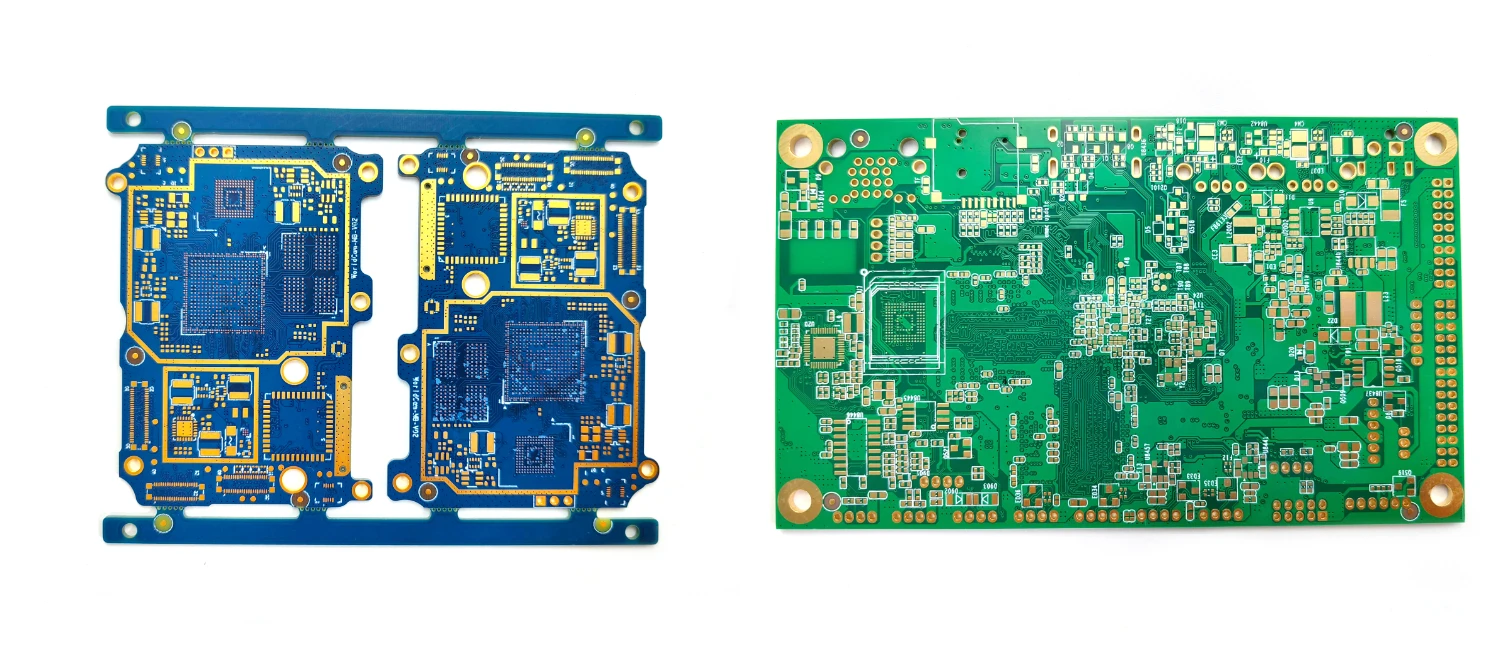
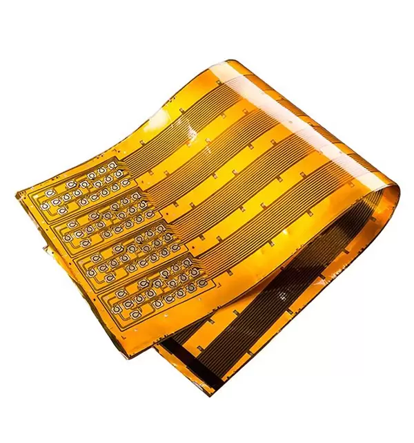
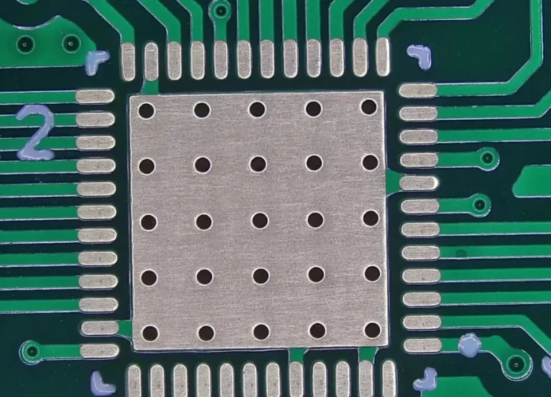
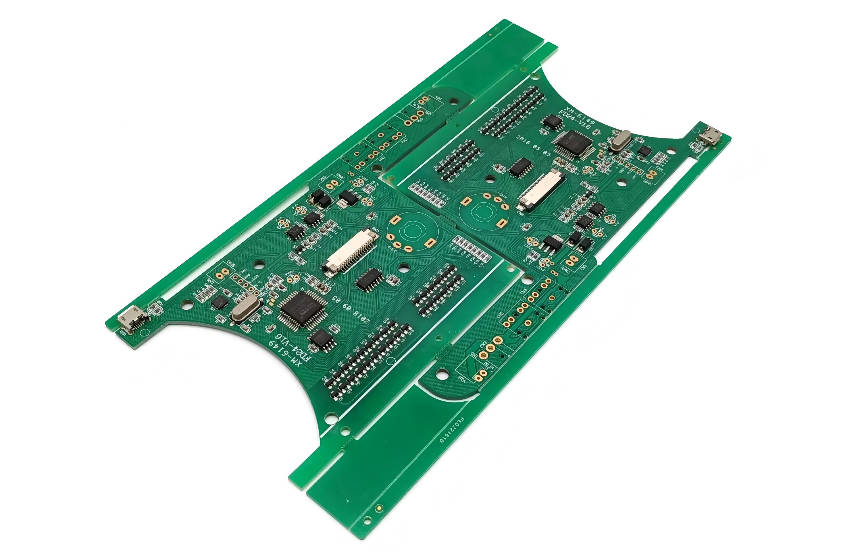
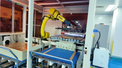
Shenzhen Benlida Circuits has been producing high-speed and RF circuit boards for more than a decade, enhanced the manufacturing system and capacity with experience and high-quality standards, perfectly match the signal integrity and impedance matching requirements of circuit boards, and providing accurate testing and analysis services.
Testing and analysis services include:
● Time Domain Reflectometer (TDR) Testing: measures the characteristic impedance of PCB traces and cables accurately, locates impedance discontinuities, and provides direct evidence for design improvement.
● Vector Network Analysis (VNA) Testing: Measures the S-parameters of the circuit, analyzing its impedance characteristics, reflection coefficient, insertion loss/return loss, and other frequency domain indicators accurately.
● Signal Integrity Testing: Verifies the eye diagram, jitter, rise time, etc., of high-speed signals, diagnosing signal quality issues caused by impedance mismatch.
RF Performance Testing: Evaluates the impedance matching and overall performance of RF components such as antennas, filters, and amplifiers.
If your circuit board is facing signal distortion, insufficient power, or high-speed circuit stability issues, please consider Benlida to know more about our manufacturing processes and quality control. With our professional manufacturing capabilities and services, we help you to achieve precise impedance matching and stable product performance!
 en
en

.webp)
 WhatsApp