Choosing a high-frequency PCB or a high-speed PCB depends on what your project needs. If your design uses radio signals or microwave frequencies, you need a High Frequency PCB. This helps keep the signal strong and meets strict impedance rules. Picking the right materials and working with manufacturers early can help you get good results and save money. When you use the right PCB for your project, your project has a better chance of succeeding.
High Frequency PCB vs High Speed PCB: Quick Guide
If you need to choose between high-frequency PCB and high-speed PCB, consider your project’s signal type, use, and the level of performance required. The table below shows the main technical differences between these two PCB types:
| Feature | High Frequency PCB | High Speed PCB |
|---|
| Signal Type | Analog RF, microwave, millimeter-wave | Digital signals with fast edge rates |
| Operating Range | 500 MHz – 100 GHz+ | 100 MHz – several GHz |
| Main Priority | Dk stability, loss tangent, phase accuracy | Signal integrity, timing, skew, crosstalk |
| Materials | PTFE, Rogers RO3003/RO4350B, Taconic, Teflon | FR4, Megtron 6, Isola I-Speed, low-loss epoxies |
| Routing Focus | Transmission lines (microstrip/coplanar) | Differential pairs, length tuning, return paths |
| Loss Sensitivity | Extremely sensitive | Medium to high sensitivity |
| Typical Industries | Radar, 5G, RF front-end, satellite, microwave sensors | Servers, CPUs, AI accelerators, telecom hardware |
When to Choose High-Frequency PCB
Pick a high-frequency PCB if your project uses analog signals at very high frequencies. These PCBs are best for things like radar, satellites, and microwave sensors. You need materials that keep signals strong and accurate. If your design uses radio waves or works above 500 MHz, this PCB is right for you. Use it when you care about phase accuracy and low signal loss.
When to Choose High Speed PCB
Pick a high-speed PCB for projects that need fast digital signals and high data transfer. These PCBs are good for servers, CPUs, and telecom hardware. If your project uses fifth-generation cellular systems or AI accelerators, you need a PCB that handles timing, signal quality, and crosstalk. High-speed PCB designs use differential pairs and length tuning to keep digital signals clear and quick.
Pick a high-speed PCB when your project needs:
●Fast digital circuits
●High data transfer rate
●Good signal quality
You can use materials like FR4 or Megtron 6 for these PCBs. They help you get good performance and save money for digital projects.
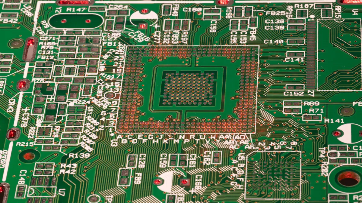
What Is a High-Frequency PCB?
A high-frequency PCB helps you control signals that move very fast. You use this board when your project needs to handle signals from 500 MHz to 2 GHz or even higher. Many people call any PCB that works above 1 GHz a high-frequency PCB. These boards use special materials and designs to keep signals clear and strong.
Key Features of High-Frequency PCBs
You should know what makes a high-frequency PCB different from other boards. Here are the most important features:
●The dielectric constant (Dk) of the material changes how fast signals move and how well the board keeps the right impedance. If the Dk is lower, signals move faster.
●The loss tangent (Df), also called dissipation factor, shows how much energy the board loses as heat. If the Df is lower, signals stay strong and do not fade.
●High-frequency PCB materials include PTFE, Rogers, and other microwave substrates. These materials help the board work well at high-frequency.
●Special ways of making the board are used to make sure it works well at high frequencies.
●You must watch out for signal loss, phase accuracy, and impedance control when you design a high-frequency PCB.
Note: Testing high frequency pcbs is important because small changes in material or design can change how the board works at high-frequency.
Typical Applications
You will see high-frequency PCB technology in many industries. Here are some common uses:
●Radar systems and microwave radio frequency communications
●Industrial automation and sensor systems
●Automotive LIDAR, radar modules, and vehicle networks
●Safety and security systems, including surveillance and wireless networks
●Advanced LED drivers and smart lighting systems
●Aerospace and defense, such as satellite communications and tactical electronics
●Medical imaging devices and patient monitoring systems
●Networking and telecommunications, including 5G modules and high-speed data links
A high-frequency PCB gives you the speed and reliability you need for these advanced uses. When you pick a high-frequency PCB, you make sure your project can handle the needs of modern high-frequency technology.
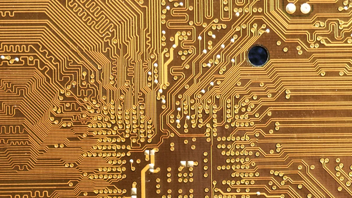
What Is a High-Speed PCB?
A high-speed PCB helps you manage fast digital signals in your electronic designs. You use a high-speed PCB when your project needs to move data very quickly. You see high-speed PCB technology in many modern devices. When you work with a high-speed PCB, you focus on keeping signals clear and fast. You need to understand how high-speed PCB design works to get the best results.
Key Features of High-Speed PCBs
You can spot a high-speed PCB by looking at its special design features. These features help you keep your signals strong and reliable. Here are the most important things you find in a high-speed PCB:
●Signal integrity matters most in a high-speed PCB. You want your signals to stay sharp as they travel across the board. You must watch for problems like reflections, crosstalk, and electromagnetic interference.
●Impedance control is key in a high-speed PCB. You keep the impedance steady so your signals do not bounce back or lose quality.
●Differential signaling is common in a high-speed PCB. You use pairs of signals that work together to cut down on noise and boost signal quality.
●Power integrity is important in a high-speed PCB. You make sure every part gets clean power. This stops problems like jitter and data errors.
You call a PCB high-speed when it handles data rates above 100 Mbps. You also see high-speed PCB designs when clock speeds go over 200 MHz. When your data rate hits 500 Mbps or more, you must pay close attention to signal integrity in your high-speed PCB.
Typical Applications
You use a high-speed PCB in many advanced projects. Here are some common places where you need a high-speed PCB:
●Communication systems need high-speed PCB designs to move lots of data fast.
●Radar systems use high-speed PCB technology to process signals quickly and accurately.
●Medical equipment relies on high-speed PCB boards for fast and safe data handling.
You also find high-speed PCB designs in computers, servers, and telecom hardware. High-speed PCB technology helps you build devices that keep up with today’s fast digital world. When you choose a high-speed PCB, you make sure your project can handle high-speed data and complex signals.
High-Frequency PCBs vs High-Speed PCBs: Applications
Industry Use Cases
You can find high-frequency PCBs and high-speed PCBs in many fields. Each one is good for different jobs. High-frequency PCBs are used when you need to send radio signals. They are found in wireless communication, radar, aerospace, and medical tools. These boards help keep signals clear and strong, even at high frequencies. High-speed PCBs are used to move digital data fast. You see them in data communication, digital signal processing, and memory systems. These boards make sure data moves quickly and stays correct. High-speed PCBs are in computers, servers, and telecom gear.
High-frequency PCBs:
●Wireless communication
●Radar systems
●Aerospace technology
●Medical devices
High-speed PCBs:
●High-speed data communication
●Digital signal processing
●Memory systems
Tip: Pick the right board by thinking about your signals and how fast they need to go.
Signal Types and Requirements
You should know what signals each board can handle. High-frequency PCBs carry analog RF or microwave signals. These signals need special care to stop loss and interference. High-speed PCBs carry fast digital signals. You must keep these signals sharp and free from mistakes.
Here is a table to help you compare the main needs for each type:
| Type of PCB | Signal Type | Frequency Range | Material Requirements | Design Focus |
|---|
| High-Frequency PCBs | RF Signals | 300 MHz to 300 GHz | PTFE, ceramics, Teflon (low Dk, low Df) | Signal integrity, low loss, minimal interference |
| High-Speed PCBs | Digital Signals | Common data transmission | FR4 (low-loss variants preferred) | Minimize signal degradation, reflections, and crosstalk |
You can also see the difference in signal types:
| PCB Type | Signal Type |
|---|
| High-Speed PCBs | Fast digital signals |
| High-Frequency PCBs | Analog RF/microwave signals |
When you choose between high-frequency PCBs and high-speed PCBs, look at your signal type and what your project needs. This helps you get the best results from your PCB.
Materials and Stackup for High-Frequency and High-Speed PCBs
Substrate Materials Comparison
You need to pick the right substrate for your multilayer PCBs. The substrate changes how signals move and how well your board works. Here are some common materials you will find in multilayer PCBs:
●FR-4 is strong and cheap. You use it in many multilayer PCBs. It does not work well for high-frequency PCBs.
●Polyimide stays strong at high temperatures. You use it in multilayer PCBs for cars and planes.
●PTFE keeps signal loss low. You use it in high-frequency PCBs for RF and microwave jobs.
●Ceramic substrates have low dielectric loss and good heat control. You use them in high-frequency PCBs and high-power multilayer PCBs.
Metal core PCBs help with heat. You use them in multilayer PCBs for LED lights and high-power electronics.
You should check the dielectric constant and loss tangent. PTFE and ceramics have low values. They keep signals strong in high-frequency PCBs.
Layer Stackup Importance
Multilayer PCBs have many copper and dielectric layers. The stackup decides how signals travel and how well your board works. A good stackup helps you keep signal integrity and power integrity in high-speed PCBs. You put signal layers next to ground planes to control impedance and cut noise. Custom stackups help you meet strict needs for high-speed PCBs and high-frequency PCBs.
Tip: Use thinner dielectric layers in high-frequency pcbs to lower signal loss. In high-speed pcbs, route traces to reduce crosstalk.
Impact on Performance
Stackup and materials change how your multilayer PCBs work. You get stable impedance and less signal loss with the right setup. You cut crosstalk by separating layers and placing ground planes well. You shield your board from electromagnetic interference with a good stackup. Low dielectric loss and low dielectric constant help signals move fast and stay strong in high-frequency PCBs. In high-speed PCBs, you need controlled impedance for clear digital signals.
Here is a table to show how stackup affects performance:
| Stackup Feature | Benefit for High-Frequency PCBs | Benefit for High-Speed PCBs |
|---|
| Thin dielectric layers | Lower signal loss | Faster signal travel |
| Ground plane placement | Better EMI shielding | Controlled impedance |
| Layer separation | Less crosstalk | Less noise |
You need to plan your multilayer PCBs well. The right materials and stackup help you get the best results for high-frequency PCBs and high-speed PCBs.
Design Challenges in High-Frequency and High-Speed PCBs
When you use high-frequency or high-speed PCBs, you face special problems. You have to plan your board very carefully. Each PCB type needs its own trace width, spacing, and stackup. You must think about signal integrity and how signals move. If you miss these details, your board might not work right.
Trace Width and Spacing
You need to pick the right trace width and spacing. In high-speed PCB design, you often use thin traces and reference planes. This helps you control impedance and keep signals strong. High-frequency PCB design may use wider or tapered traces. This matches impedance and lowers signal loss. You should keep traces apart to stop crosstalk. If traces are too close, signals can mix and cause problems. You also need to plan your layer stack-up well. A good stackup helps you manage return paths and block noise.
Signal Integrity and Reflection
Signal integrity is very important in both PCB types. You want signals to stay clear and strong. Problems like reflections can change your signals and cause mistakes. Impedance mismatches often cause these reflections. You can use resistors, good termination, and even trace width to help. Crosstalk and electromagnetic interference can also hurt your board. You must design your board to lower these risks and keep signals clean.
Note: Signal loss can happen from high-frequency effects like dielectric loss and the skin effect. You need to pick good materials and design your board to fight these losses.
Manufacturing Tolerances
Manufacturing tolerances are very important for your board’s success. For new things like 5G and IoT, you need tighter tolerances. Small changes in trace width or thickness can cause phase errors or signal problems. In high-frequency PCB design, even a small change in thickness can shift your signal’s phase. Controlled impedance is important for both PCB types. You must work with your manufacturer to meet these strict needs. This helps you keep signals strong and your board working well.
Cost Comparison: High-Frequency vs High-Speed PCBs
Material and Manufacturing Costs
You need to look at both material and manufacturing costs when you choose between high-frequency and high-speed PCBs. High-frequency PCBs often cost more because they use special materials and need extra steps during production. Here is what you can expect:
●High-frequency PCB materials usually cost between $90 and $150 per square meter. The price depends on the supplier and the thickness you need.
●If you want advanced surface finishes, you will pay an extra $15 to $30 per square meter. These finishes help your board last longer and work better at high frequencies.
●Thicker copper and precise drilling can add $10 to $20 per square meter. These features make your board stronger and more reliable.
●For a 6-layer high-frequency PCB, the total cost can range from $80 to $180 per square meter. Custom designs and small batch sizes can push the price higher.
●High-speed PCBs often use standard materials like FR4, which cost less. You can save money if your project does not need special high-frequency features.
Design and Testing Costs
Design and testing also affect your total cost. High-frequency PCBs need tighter tolerances. This means you must pay more for careful manufacturing. Costs can go up by 20% to 40% compared to boards with standard tolerances. You must also make sure trace widths and impedance stay consistent. This adds to the design work and the price.
High-speed PCBs often need advanced features like impedance control and RF design. You may need special tools and experts to finish your design. Testing and simulation for high-speed circuits also add to the cost. These steps help you catch problems early and make sure your board works well.
| Cost Factor | High-Frequency PCB | High-Speed PCB |
|---|
| Material Cost | High | Medium |
| Manufacturing Tolerance | Very tight (costly) | Tight (less costly) |
| Design Complexity | High | High |
| Testing & Simulation | Moderate | High |
You should plan your budget based on your project’s needs. High-frequency PCBs cost more for materials and precision. High-speed PCBs cost more for design and testing.
How to Choose the Right PCB for Your Project
Key Selection Factors
You need to look at several important factors before you pick between high-frequency PCBs and high-speed PCBs. Each project has its own needs. You want your board to work well and stay within your budget.
Signal Type: Think about the signals in your project. High-frequency PCBs work best for analog RF or microwave signals. High-speed PCBs are better for fast digital signals.
Frequency Range: Check the frequency range your board must handle. High-frequency PCBs support 500 MHz to 100 GHz or more. High-speed PCBs usually work from 100 MHz up to several GHz.
Material Properties: Pick materials that match your frequency range. For example, telecommunications need materials for 5-50 GHz. Automotive radar may need materials for 50 GHz or higher. Rogers RO4000 and PTFE are good for high-frequency PCBs. FR4 and Megtron 6 are common for high-speed PCBs.
Controlled Impedance: You must keep a 50Ω impedance match. This helps stop signal reflections and keeps your signals clear.
Signal Integrity: Look for low signal loss and little crosstalk. This is important for both high-frequency PCBs and high-speed PCBs.
Thermal Stability: Make sure your board can handle heat. High-speed PCBs often get hot, so you need materials that stay strong.
Shielding: Use shielding to stop unwanted signals from getting in or out. This is important for both types of boards.
Environmental Conditions: Think about where your board will work. High temperatures or humidity can change how your board works. Pick materials that can handle these conditions.
Mechanical Properties: Decide if you need a flexible or rigid board. Some projects need boards that bend, while others need strong, stiff boards.
Cost vs. Performance: High-performance materials cost more. You need to decide if the extra cost is worth it for your project.
Practical Checklist
You can use this checklist to help you choose the right board for your project. Go through each step and see which type fits your needs.
1. What type of signal does your project use?
Analog RF or microwave → Choose high-frequency PCBs.
Fast digital signals → Choose high-speed PCBs.
2. What is the highest frequency in your design?Above 500 MHz (especially over 1 GHz) → High-frequency PCBs.
100 MHz to several GHz (digital) → High-speed PCBs.
3. What industry or application is this for?Radar, satellite, 5G, or automotive radar → High-frequency PCBs.
Servers, routers, computers, or telecom hardware → High-speed PCBs.
4. Do you need special materials for low loss or high stability?Yes → Use materials like PTFE, Rogers, or ceramics.
No → Standard FR4 or low-loss epoxies may be enough.
5 . Does your design need tight impedance control (50Ω)?Yes → Both high-frequency PCBs and high-speed PCBs can do this, but check your material choice.
6. Will your board face high heat or tough environments?
Yes → Pick materials with good thermal and environmental stability.
7. Is cost a big concern for your project?
Yes → Try to use standard materials and simple designs.
No → Invest in high-performance materials for better results.
| Decision Point | High-Frequency PCBs | High-Speed PCBs |
|---|
| Signal Type | Analog RF, microwave | Fast digital |
| Frequency Range | 500 MHz – 100 GHz+ | 100 MHz – several GHz |
| Main Materials | PTFE, Rogers, ceramics | FR4, Megtron 6, Isola |
| Application Examples | Radar, 5G, automotive radar | Servers, routers, telecom |
| Cost | Higher | Medium to high |
You can use this checklist for every new project. It helps you make smart choices and avoid mistakes. Picking the right board gives your project the best chance to succeed.
You can find the biggest differences between high-frequency and high-speed PCBs in this table. Each type is good for different jobs and design needs.
| Aspect | High-Frequency PCBs | High-Speed PCBs |
|---|
| Applications | Wireless, radar, sensors | Computers, network devices |
| Materials | Low-loss glass fiber, PTFE | Low Dk materials for speed |
| Design Focus | Crosstalk, attenuation, harmonics | Transmission lines, signal integrity |
| Manufacturing | Strict loss control, shielding | Complex routing for fast signals |
| Testing | Specialized frequency testing | Advanced data rate testing |
You should use the checklist to help you pick the right board. If you are not sure, ask an expert for help. Here are some tips for better results: Use simulation tools to test your design. Choose materials with low Dk and Df. Make sure your PCB can handle heat and noise.
After you pick your board, follow these steps: First, check your design with simulation. Then, use design for manufacturability to keep your project moving forward.
About the auther:

Sonic Yang
As a major of Electronics and Mechanical Automation, Sonic has been engaged in PCB design, R&D, manufacturing of eletronics for around 22 years, as engineering director and coordinates with supply chain(components&CNC parts), providing professional supports and consults for global customers.
 en
en

.jpg)

 WhatsApp