You must watch out for signal loss and how well electricity moves when picking PCB materials for high-frequency PCB designs. Stable properties help you stop problems like distortion and interference. If you pick the right materials, your circuits will work well.
Dielectric Properties in High-Frequency PCB Selection
Low Dielectric Constant (Dk) for Signal Integrity
When you make a high-frequency PCB, you need to look at the dielectric constant. This number, called Dk, shows how quickly signals move in the material. If the dielectric constant is high, signals move more slowly. This can make your circuit have timing issues. For high-frequency and RF uses, pick materials with a dielectric constant under 4. Many people say a Dk of about 3.0 works best.
- A lower dielectric constant helps signals go faster.
- A substrate with a Dk of 3.0 can make signals about 20% faster than one with a Dk of 4.5.
- Faster signals mean less reflection and better PCB performance.
Low Loss Tangent (Df) for Efficient Performance
Loss tangent, or Df, tells you how much energy your circuit loses as signals move through the PCB. You want this number to be very low, especially for high-frequency and RF designs. Even small losses can make your circuit work worse.
- A low Df keeps signals strong and clear.
- For high-frequency PCB materials, try to get a Df under 0.005.
- For example, a material with a Df of 0.001 loses much less signal than one with a Df of 0.02 at 10 GHz.
Here is a table that shows some Df values:
| Material Type | Typical Df Value | Frequency Range |
|---|
| High-Frequency Laminates | 0.001 - 0.003 | Above 5 GHz |
| Standard FR-4 | 0.02 | Up to 1 GHz |
Matching Dielectric Properties to Application Frequency
You need to match the dielectric properties of your material to your device’s frequency. If you are making a 5G antenna or another high-frequency device, use a material like Rogers with a dielectric constant close to 3.0. This helps keep your impedance and signal integrity steady.
- The dielectric constant changes the wavelength of your signal, which matters for small RF circuits.
- The thickness of your laminate changes the trace width you need for the right impedance.
- Always check that your material’s properties fit your circuit’s frequency.
Material Stability and CTE Compatibility
Consistency Across Frequency and Temperature
Pick materials that do not change much when hot or at different frequencies. If the material changes its dielectric constant or shape, your high-frequency PCB may lose signals or stop working. High-frequency and RF circuits often work in hard places. You want your PCB to keep its shape and work well, even if it gets hot. High-speed PCB materials must stay strong at high temperatures. If the material is not stable, you can lose signals, and your parts may not last long. A low and steady dielectric constant helps you stop signal problems. When the frequency is higher, you need materials that lose less energy and handle heat better.
Coefficient of Thermal Expansion (CTE) Considerations
CTE shows how much a material grows when it gets hot. If your PCB and its parts grow at different speeds, cracks or broken solder joints can happen. For example, silicon chips have a CTE of about 6 ppm/°C, but many PCB materials grow more. This difference can make your circuit not work well. The table below shows how some materials are different:
| Material Type | X-Y CTE (ppm/°C) | Z-CTE (ppm/°C) | Tg Range (°C) | Typical Applications |
|---|
| Rogers4350 | 12-15 | 40-50 | >280 | RF/Microwave, high-frequency |
You should always look at CTE values when picking materials for high-frequency or RF designs.
Selecting Materials for Reliable High-Frequency PCB Operation
You want your circuit to last a long time, even in tough places. Picking the right material helps you stop problems like solder joints breaking, layers coming apart, and vias cracking. These problems happen more in high-frequency and RF boards because they get hot and cool down fast. Small parts like microvias can break even more easily. The most important things for good operation are: dielectric constant for steady impedance, low loss for strong signals, thermal stability for working at different temperatures, moisture resistance for safety, and mechanical strength for hard places.
Thickness and Copper Foil in PCB Materials Selection
Thickness Impact on Impedance Control
It is important to look at the thickness of your PCB material. This matters a lot when you design high-frequency circuits. The thickness changes the impedance of your traces. Impedance affects how well signals move. If you make the dielectric thicker, the impedance gets higher. If you make it thinner, the impedance gets lower. This is important for high-frequency PCB and RF designs. It helps keep signals strong and clear.
- A thicker dielectric gives you higher impedance.
- A thinner dielectric gives you lower impedance.
- Controlling impedance is key for high-speed and RF circuits.
Here is what happens with microstrip impedance:
- If you make the dielectric thicker, like from 0.2 mm to 0.4 mm, the impedance can go from 50 ohms to about 65 ohms.
- A thicker dielectric lowers the capacitance between the trace and ground, so impedance goes up.
- A thinner dielectric raises the capacitance, so impedance goes down.
PCB thickness is very important for controlled impedance. This is even more true at higher frequencies. You need to pick the right thickness for your circuit.
Copper Foil Type for Signal Loss Reduction
The type of copper foil is also important for high-frequency and RF PCB designs. How rough the copper is changes how signals move. At high frequency, signals travel mostly on the copper’s surface. If the copper is rough, you lose more signal and get more distortion. Smoother copper foils help keep signals strong and reduce loss.
| Type of Copper | Description | Roughness |
|---|
| Electrodeposited | Rougher surface on one side | Highest (above 1 um) |
| Reverse treated | Surface treatment to reduce roughness | Moderate (0.5-1.5 um) |
| Rolled-annealed | Smoother, denser surface | Low (0.25-0.5 um) |
| Ultra-low profile | Extra treatments for smoothness | Lowest (<0.3 um) |
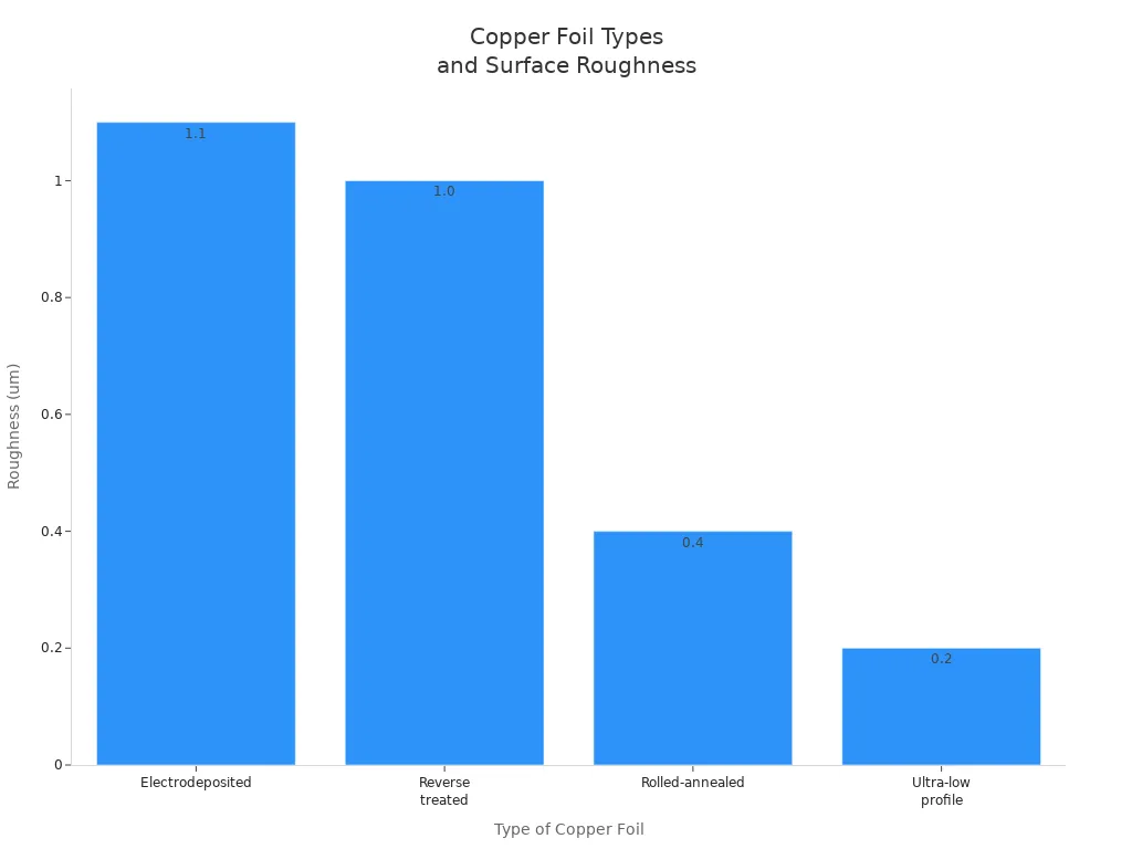
Rough copper makes resistance and signal loss worse. Ultra-smooth copper foils help fix these problems, but they cost more money. You can lower signal loss by picking the right copper foil and making good trace shapes.
Balancing Design and Manufacturability
You need to balance how well your board works and how easy it is to make. Thicker copper lets you use more current and helps with heat. But it is harder and costs more to make. Most boards use 1 oz copper because it works well and is not too expensive. If you want thicker copper, check if it is worth the extra cost.
- Rough copper makes resistance and signal loss worse.
- Ultra-smooth copper lowers loss but costs more.
- You can use computer tools to help design your board.
Think about what your board needs to do, where it will be used, and how good the signals must be. Thinner copper and low-loss materials are best for fast signals. Use thicker copper and heat-resistant materials if your board gets hot.
Manufacturability and Fabrication-Friendly Materials
Compatibility with Standard PCB Processes
When you pick materials for a high-frequency PCB, make sure they work with normal factory steps. Some materials, like PTFE, Rogers, and ceramic-filled laminates, are easy to use in most PCB factories. These materials have strong electrical properties and stay stable when hot. FR-4 is used a lot, but it is better for lower frequency circuits. For RF and high-frequency designs, check the table below to see your choices:
| Material | Compatibility with Standard Processes | Electrical Properties | Thermal Stability |
|---|
| PTFE | High | Superior | Excellent |
| Rogers Materials | High | Superior | Good |
| Ceramic-Filled | High | Superior | Good |
| FR-4 | Moderate | Standard | Moderate |
Ease of Assembly for High-Frequency PCB Designs
You may have special problems when you put together high-frequency and RF PCBs. You need to keep layers lined up and control how you press them together. You also need to make sure vias and copper layers stay strong. If you do not handle heat well, your board can break or stop working properly. Some common problems are:
- Heat problems that can make the board expand or come apart.
- Back-drilling to stop signals from bouncing in microvias.
- Solder masking can cause more loss if done wrong.
- Plasma etching which needs careful work for clean boards.
You can make building easier by picking materials that handle heat well and keep their shape. This helps you stop signal loss and makes your board last longer.
Working with PCB Manufacturers for Optimal Selection
You should talk to your PCB maker early when you design your board. They can help you pick the best material for your frequency and RF needs. Makers know which materials are easy to use and which ones give you the best mix of performance and price. If you use many layers or mix materials, your maker can help you compare them. Working together helps you avoid problems and get a PCB that works well and is easy to make.
Note: Working with your maker helps you find the best balance between how well your board works, how easy it is to make, and how much it costs. This is important for good high-frequency and rf pcb designs.
Cost vs. Performance in High-Frequency PCB Selection
Evaluating Material Costs and Performance Gains
You have to think about how much money you can spend and how well you want your high frequency pcb to work. Some materials are much more expensive than others. For example:
- Rogers laminates can cost from $5 to $20 for each square foot. The price changes with the grade and thickness.
- PTFE and ceramic-filled laminates can cost over $30 for each square foot. These are rare and hard to make.
- PTFE-based materials give you low loss and steady properties, but they cost more than FR-4.
- RF Polyurethane materials also cost more than FR-4, but they work better at high frequencies.
You should decide how much performance you really need. If your design needs very low loss and strong signals, you may have to pay more for special materials. If your design works at a lower frequency or does not need the best performance, you can use regular materials and save money.
When to Invest in Premium PCB Materials
Sometimes, you need to use expensive materials even if they cost more. The table below shows when it is a good idea:
| Scenario | Justification |
|---|
| High signal integrity | Needed for RF designs in telecom and aerospace, where you want low loss. |
| Frequencies above 1 GHz | Rogers and similar materials keep your PCB working well at high frequency. |
| Long-term reliability | Premium materials help your RF circuits last longer and avoid costly repairs. |
If your project must last a long time or work at a very high frequency, you should pick premium materials. This helps you stop signal loss and keeps your PCB safe.
Strategies for Cost-Effective High-Frequency PCB Design
You can use smart ways to save money and still get good performance:
- Use hybrid designs that mix regular and high-frequency materials.
- Try to use fewer layers in your PCB by using good design tools.
- Make tolerances looser in places that do not need perfect RF performance.
- Do not use shapes and features that are hard to make.
- Work with manufacturers who know how to save costs.
If you follow these steps, you can get a high-frequency PCB that works well and does not cost too much. Always pick materials that fit what you really need. This helps you get good value and strong RF performance.
Reliability and Environmental Factors in PCB Materials Selection
Long-Term Reliability and Moisture Resistance
You need to think about how your PCB handles water and time. High humidity can cause big problems for high-frequency PCB designs. If the humidity goes over 60%, the chance of failure gets higher. In tropical places, humidity can reach 80%. Water in the air can cause rust, short circuits, and signal loss. These problems can ruin how your circuit works. You should pick materials that fight moisture and keep working well over time. Tests like the Temperature Humidity Bias Test and Highly Accelerated Stress Test show how your PCB works in tough places.
Here are some important things for long-term reliability:
| Property | Description |
|---|
| Low Dielectric Constant | Keeps signal speed steady and controls impedance. Best values are 2.2 to 3.5. |
| Low Dissipation Factor | Reduces loss, which is key for high-speed circuits. |
| Thermal Stability | Let's materials handle temperature changes without losing performance. |
| Moisture Resistance | Helps your PCB last longer in harsh environments. |
Thermal Performance and Heat Resistance
You must control the heat in your PCB to keep it safe. Good thermal management stops overheating and keeps your circuit working. If your material cannot handle heat, parts may break. Too much heat can cause signal loss and make your board not last long. You want materials that move heat away from parts and keep things cool.
- Good thermal management helps your parts last longer.
- Heat control lowers the chance of sudden shutdowns.
- Keeping the right temperature protects your high-frequency circuits from failing early.
- Better heat control also means less noise and better signals.
Meeting Industry Standards for High-Frequency PCB
You should always check if your materials meet industry rules. These rules help you make sure your PCB works well and lasts a long time. For high-frequency designs, you need materials with a low dielectric constant and low loss. IPC-6018D is an important rule for high-frequency boards. It checks if your material passes key tests. Factories also look for evenness and matching thermal expansion. This stops layers from peeling apart and keeps your PCB strong.
| Key Aspect | Description |
|---|
| Low Dielectric Constant (Dk) | Reduces signal loss and keeps waveforms clear. |
| Low Dissipation Factor (Df) | Cuts down on energy loss, which is vital for high-frequency uses. |
| IPC-6018D Compliance | Make sure your materials pass tests for high-frequency boards. |
| Material Uniformity | Checks for even performance across all pPCBs |
| Thermal Expansion Matching | Stops layers from peeling apart under stress. |
You need to think about how well your board works, how easy it is to make, how much it costs, and how long it lasts. Always figure out what your board needs for electricity and heat first. Use this checklist to help you pick materials for high-frequency boards:
| Checklist Item | What to Check For |
|---|
| Dielectric constant (Dk) | Less than 4 |
| Loss tangent (Df) | Less than 0.005 |
| Thermal conductivity | Above 0.5 W/mK |
| Glass transition temperature | Above 170°C |
Talk to PCB makers who know a lot. This helps you avoid mistakes and get the best board.
FAQ
What is the most important property for high-frequency PCB materials?
You need to look at the dielectric constant, called Dk. A low Dk makes signals move faster. It also helps your circuit work better. Try to pick materials with Dk under 4 for the best results.
Why does copper foil roughness matter in high-frequency PCBs?
Copper foil roughness changes how signals move. Smoother copper lets signals travel with less resistance. You get better performance and less distortion with ultra-low profile copper.
Can you use standard FR-4 for high-frequency designs?
You can use FR-4 for lower frequencies. But it loses signals at high frequencies. For RF or microwave circuits, pick special materials like Rogers or PTFE for better results.
How do you balance cost and performance in material selection?
You can mix regular and high-frequency materials. Use premium materials only where you need them. This helps you save money and still get strong signal performance.
About the author:

Sonic Yang
As a major in Electronics and Mechanical Automation, Sonic has been engaged in PCB design, R&D, and manufacturing of electronics for around 22 years, as engineering director and coordinates with the supply chain(components and CNC parts), providing professional support and consultation for global customers.
 en
en


 WhatsApp