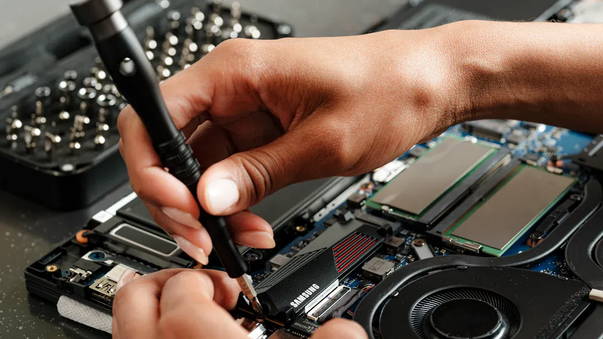
Repairing a USB port on a pcb assembly for usb port carrier applications starts with accurate diagnosis. Identifying whether the issue is software-related or caused by physical damage helps technicians choose the best repair method and increases the chance of restoring function. Main repair options include software troubleshooting for invisible issues, professional re-soldering or port replacement for confirmed damage, and temporary solutions like using a certified USB-C dock. Safety and quality matter most. Always check that USB connector shells meet electrical safety standards, such as NOM-019-SCFI-2018, to prevent risks.
●USB connector shells should comply with electrical safety regulations.
●Look for the NOM mark to ensure proper creepage distance and reduce shock risk.
Expert assembly and inspection, as provided by BENLIDA, ensure reliable usb port repair. This guide offers practical, step-by-step advice.
USB Port Repair Methods
Software Troubleshooting
Technicians often begin with software troubleshooting when repairing usb connectors. This step helps determine if the issue comes from the device’s operating system or driver settings. Restarting the device can resolve minor glitches. Updating drivers for usb connectors may restore communication. Device managers in computers allow users to check the status of usb connectors and reinstall drivers if needed. Sometimes, disabling and re-enabling the port in the system settings can fix recognition problems. Software troubleshooting is essential before moving to physical repairs.
Cleaning and Inspection
Physical faults in usb connectors require careful cleaning and inspection. Dust and debris can block connections and cause intermittent failures. Use compressed air to remove particles from usb connectors. Inspect the solder joints around the port for bent or misaligned pins. These issues can disrupt data and power transmission. Look for dull, cracked, or incomplete solder joints, which may indicate cold solder joints. Examine the PCB surface for scratches or cracks that might sever copper traces. Missing components or burns on the board can interrupt circuit paths. BENLIDA’s PCB Assembly for USB Port Carrier uses high-quality FR-4 TG150 material and lead-free HASL, making inspection easier and safer. Proper cleaning and inspection help maintain the reliability of usb connectors.
Re-soldering and Replacement
If cleaning and inspection reveal damage, re-soldering or replacing usb connectors becomes necessary. Use a soldering iron with a fine tip for precision. Wear safety glasses and use proper ventilation. BENLIDA’s assemblies support both SMT and through-hole techniques, allowing for flexible repair options. Remove damaged usb connectors carefully to avoid harming the PCB. Apply fresh solder to secure new connectors. Check for solid connections and test the port after repair. Quality control, as practiced by BENLIDA, ensures that repaired usb connectors meet performance standards. Always follow safety protocols and use the correct tools for lasting results.
PCB Assembly for USB Port Carrier: Repair Steps
Tools and Materials
Repairing a pcb assembly for usb port carrier requires the right tools and materials. A technician should prepare a precision soldering iron with a fine tip, lead-free solder wire, and flux. A magnifying glass or inspection microscope helps identify small defects. Use ESD-safe tweezers and a solder sucker for removing excess solder. Isopropyl alcohol and lint-free wipes clean the board after soldering. Compressed air removes dust and debris from the pcb-mounted usb receptacle. Safety glasses and an ESD wrist strap protect both the technician and the assembly.
The choice of materials impacts the repair process. BENLIDA’s use of FR-4 TG150 material ensures the board can withstand high temperatures during soldering. The lead-free HASL finish provides a reliable surface for soldering, reducing the risk of poor connections. These features support consistent results when replacing your pcb usb or repairing damaged ports.
Step-by-Step Guide
A systematic approach increases the success rate of repair. Follow these steps for a pcb assembly for usb port carrier:
1.Rule out software issues first. Restart the device and check for errors in Device Manager or System Information. Update chipset and USB controller drivers from the manufacturer’s website.
2.Test the port with at least two known-good USB cables and two different peripherals. If all fail, hardware is likely the cause.
3.Inspect the port visually. Use a flashlight and magnifier to look for bent pins, discoloration, or debris. Do not insert tools at this stage.
4.Check for mechanical play. Gently move the port shell. Any movement suggests a broken solder joint.
5.Decide on the next step. If there is no movement and no visible damage, continue with software checks. If there is movement or visible damage, proceed with physical repair.
6.Remove the damaged port. Use a soldering iron and solder sucker to desolder the pins and shell. Take care not to overheat the FR-4 TG150 substrate, which resists delamination but still requires careful handling.
7.Clean the pads with isopropyl alcohol. Remove any old solder and inspect for lifted pads or traces.
8.Place the new port. Align it carefully and secure it with ESD-safe tweezers.
9.Solder the pins and shell. Apply lead-free solder and flux for a strong connection. The lead-free HASL finish on BENLIDA boards supports reliable soldering.
10.Inspect the solder joints. Use a magnifier to check for cold joints or bridges.
11.Clean the area again. Remove any flux residue with alcohol.
12.Test the repaired usb port with multiple devices to confirm proper function.
Tip: Always document each step and take photos if possible. This helps with troubleshooting and quality assurance.
Safety and Quality Checks
Safety and quality are essential during repair. Wear safety glasses and use an ESD wrist strap to prevent static damage. Work in a well-ventilated area to avoid inhaling fumes. Handle the pcb assembly for usb port carrier by the edges to avoid contaminating the surface.
BENLIDA’s quality control procedures set a high standard. Each board undergoes incoming material checks, SMT assembly inspection, and soldering quality assessment. Functional testing ensures that every repaired usb port meets performance requirements. The FR-4 TG150 material provides exceptional thermal stability, with a glass transition temperature of 157°C and a decomposition temperature up to 352°C. This minimizes the risk of board damage during soldering. The lead-free HASL finish supports reliable soldering and reduces the chance of exposed copper.
Reliability testing includes thermal cycling and environmental stress tests. These procedures validate the durability of the pcb assembly for usb port carrier in real-world conditions. Following these best practices ensures a safe and reliable repair.
Common Problems of USB PCB
Understanding the common problems of usb pcb helps technicians and engineers maintain reliable device performance. The most frequent usb pcb problems involve loose or broken ports, soldering issues, and failures in signal or power delivery. Each problem requires a specific approach for diagnosis and repair.
Loose or Broken Ports
Loose or broken ports are a leading cause of usb pcb problems. These issues often result from repeated plugging and unplugging, mechanical stress, or accidental impacts. Diagnosing faulty usb pcb ports starts with a careful visual inspection. Look for physical damage, misalignment, or movement in the ports. Electrical testing with a multimeter can confirm if the connection is unstable or broken. BENLIDA’s assemblies use robust FR-4 TG150 material and precise connector mounting to reduce the risk of loose ports. When a port feels wobbly or fails to hold a cable securely, replacement is usually necessary.
Checklist for Diagnosing Loose or Broken Ports:
●Inspect ports for visible cracks or bent pins.
●Gently wiggle the ports to check for movement.
●Use a multimeter to test continuity between the port pins and the PCB traces.
Soldering Issues
Soldering issues are another source of usb pcb problems. Poor solder joints can cause intermittent connections or complete failure of ports. The main causes include insufficient heat during soldering, contamination on the soldering surface, and movement of ports before the solder cools. BENLIDA’s quality control process includes thorough inspection of all solder joints to ensure strong and reliable connections.
Tip: Always clean the soldering area and use the correct temperature to avoid weak joints.
When diagnosing soldering problems, check for dull, cracked, or incomplete joints around the ports. Reflowing or re-soldering the affected area often restores proper function.
Signal and Power Failures
Signal and power failures in usb pcb problems can stop ports from working entirely. Accurate diagnosis involves several steps:
- Gather information about the symptoms and when the failure occurs.
- Visually inspect the PCB for burnt components, cracked joints, or corrosion near the ports.
- Use a multimeter to verify input voltage and check the main voltage rails at the ports.
- Test components like resistors and capacitors connected to the ports.
- Trace signals with an oscilloscope to find where the signal is lost.
BENLIDA’s assemblies undergo functional testing to catch these issues before shipping. If a port does not deliver power or data, follow these steps to isolate and repair the fault. Addressing these usb pcb problems quickly ensures long-term reliability and reduces downtime caused by faulty usb pcb ports.
Method Selection and Cost
Choosing the Right Repair Approach
Selecting the best repair method depends on the problem and the skill level of the technician. If the issue is minor, such as a loose connector or simple soldering fault, a basic repair may be possible. For complex faults, like damaged traces or repeated failures, professional help is recommended. BENLIDA offers advanced inspection and testing. Their technicians understand what makes a pcb layout stop working and can restore function with precision. When the port shows signs of physical damage or the board has multiple faults, professional repair ensures reliability.
Note: Always check the types of usb pcb connectors before starting any repair. Different connectors require specific tools and techniques.
DIY vs. Professional Repair
DIY repair appeals to those with basic electronics knowledge. It saves money and time for simple fixes. However, mistakes can cause further damage. Professional repair provides expertise and access to specialized equipment. BENLIDA uses quality control and functional testing to address what makes a pcb layout stop working. Their team handles all types of usb pcb connectors, ensuring proper assembly and lasting performance.
DIY Pros:
●Lower cost
●Quick for minor issues
DIY Cons:
●Risk of damaging the pcb
●Limited access to advanced tools
Professional Pros:
●High-quality results
●Thorough inspection and testing
Professional Cons:
●Higher cost
●Longer turnaround for complex repairs
Cost and Time Estimates
Repair costs vary based on the method and complexity. The table below shows typical estimates:
| Repair Method | Estimated Cost | Time Required |
|---|
| DIY (simple fix) | $10-$30 | 30-60 minutes |
| Professional (basic) | $40-$80 | 1-2 days |
| Professional (complex) | $100+ | 3-5 days |
DIY repairs cost less but may not solve all issues. Professional services, such as those from BENLIDA, offer reliable solutions for all types of usb pcb connectors. They also address what makes a pcb layout stop working, ensuring the usb port functions as intended.
Avoiding Mistakes in USB Port Repair
Preventing PCB Damage
Mistakes during repair can damage the printed circuit board and affect device performance. One common error is applying too much heat when soldering. Excessive heat can lift pads or break traces, which interrupts the flow of power. Always use a temperature-controlled soldering iron and avoid holding the tip on the pad for too long. Another mistake is using the wrong type of solder or flux. Lead-free solder, like that used on BENLIDA boards, helps maintain strong connections and supports safe power delivery. ESD (electrostatic discharge) can also harm sensitive components. Wear an ESD wrist strap and work on an anti-static mat to protect the board.
BENLIDA’s quality assurance practices help prevent these errors. The table below shows how their process supports reliable repairs:
| Step | How It Helps Prevent Errors |
|---|
| Prevention | Stabilizes solder paste and controls inputs to avoid defects. |
| Detection | Finds placement and solder issues early in the assembly process. |
| Verification | Confirms the board works as intended when power is applied. |
Tip: Always inspect the board before and after repair to catch any signs of damage.
Ensuring Long-Term Reliability
Long-term reliability depends on careful repair and thorough testing. Weak solder joints can cause intermittent power loss or data errors. Make sure each joint is shiny and smooth, which indicates a solid connection for power flow. Clean away all flux residue, as leftover chemicals can corrode traces and disrupt power delivery over time. Test the repaired port with several devices to confirm stable power and data transfer.
BENLIDA’s inspection and functional testing ensure that every usb port meets strict standards. Their process checks for consistent power delivery and verifies that all connections perform under real-world conditions. Following these best practices helps prevent future failures and keeps devices running smoothly.
Repairing usb pcb assemblies requires careful attention to connectors. Technicians inspect connectors, clean connectors, and test connectors. Quality materials support connectors. Proper tools help connectors. BENLIDA offers support for connectors. Safety protects connectors. Reliability ensures connectors work. For complex usb pcb repairs, professional services help connectors. Always check connectors. Use best practices for connectors. Document connectors. Inspect connectors. Test connectors. Clean connectors. Replace connectors. Solder connectors. Align connectors. Secure connectors. Verify connectors. Confirm connectors. Maintain connectors. Upgrade connectors. Monitor connectors. Troubleshoot connectors. Evaluate connectors. Select connectors. Install connectors. Remove connectors. Store connectors. Handle connectors. Protect connectors. Label connectors. Organize connectors. Review connectors. Consult experts for connectors. Rely on BENLIDA for connectors. Trust connectors.
Quality and safety matter for every usb pcb repair. Professional support from BENLIDA ensures connectors meet high standards.
About the author:

Sonic Yang
As a major in Electronics and Mechanical Automation, Sonic has been engaged in PCB design, R&D, and manufacturing of electronics for around 22 years, as the engineering director, and coordinates with the supply chain(components and CNC parts), providing professional support and consulting for global customers.
 en
en

 WhatsApp