Ceramic PCBs stand out as a strong choice when electronics demand high reliability and superior performance. Imagine a power module in an electric vehicle or a 5G base station, where heat and signal loss can lead to failures. In such cases, ceramic materials offer excellent thermal management and electrical insulation. Material selection plays a critical role in the outcome of a PCB. As shown below, properties like thermal conductivity and coefficient of thermal expansion directly impact device reliability and performance:
| Property | Impact on Performance | Example Materials |
|---|
| Thermal Conductivity | High thermal conductivity prevents heat damage and device failure. | Ceramic (up to 220 W/mK) |
| Coefficient of Thermal Expansion | Low CTE reduces stress, increasing reliability. | Ceramic (6-8 ppm/°C) |
Choosing ceramic means leveraging advanced manufacturing and material science for demanding applications, but it also requires weighing cost and handling challenges.
●Ceramic PCBs excel in high-performance applications due to their superior thermal conductivity, making them ideal for electric vehicles and 5G systems.
●These PCBs offer excellent electrical insulation, ensuring stable signal quality and reduced signal loss in high-speed electronics.
●While ceramic PCBs provide high reliability and durability, they come with higher costs and require careful handling during manufacturing.
●Engineers should consider ceramic PCBs for environments with extreme temperatures and mechanical stress, while alternatives like FR-4 may be better for less demanding applications.
●Customization options in ceramic PCB production allow for tailored solutions, but they also present challenges that require careful planning and quality control.
.png)
What Are Ceramic Substrate PCBs?
Definition and Structure
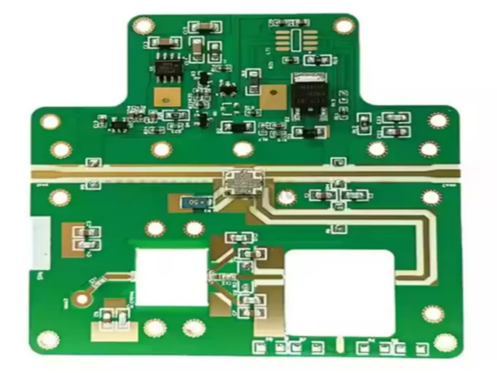
Ceramic substrate PCBs represent a specialized class of circuit boards designed for demanding environments. Unlike traditional PCB types, ceramic substrate PCBs use advanced ceramic materials as the base layer. This structure provides several unique benefits. Ceramic circuit boards offer higher thermal conductivity, chemical erosion resistance, and mechanical strength. The compatibility with the coefficient of thermal expansion of electronic components helps prevent stress and failure. Ceramic substrate PCBs also allow for high-density tracing, which supports compact designs and efficient layouts.
Common Ceramic Materials (Alumina, AlN, SiC)
Manufacturers select advanced ceramic materials based on the requirements of the application. The most widely used options include alumina, aluminum nitride, and silicon carbide. Each material offers distinct advantages for ceramic circuit boards.
| Ceramic Material | Key Characteristics | Applications |
|---|
| Alumina | Strong electrical insulation, cost-effective, reliable, versatile forms | Automotive, telecommunications, medical |
| Aluminum Nitride | High thermal conductivity, excellent electrical insulation, withstands high power. | Power electronics, LED lighting, high-performance computing |
| Silicon Carbide | Exceptional thermal stability, supports high voltage, and resists extreme environments. | Aerospace, industrial power modules, EV systems |
Alumina is popular for its reliability and cost efficiency. Aluminum nitride excels in thermal management and high-power applications. Silicon carbide stands out in extreme temperature and high-voltage scenarios.
Key Applications in Electronics
Ceramic substrate PCBs play a vital role in many industries. Their unique properties make them ideal for applications that require high reliability and performance. Ceramic circuit boards are common in electric vehicles, aerospace, and 5G communication systems. These industries demand superior thermal management and mechanical strength.
| Industry/Application | Reason for Adoption |
|---|
| Military Applications | High reliability and performance requirements |
| Space Program Components | Need for thermal stability and durability |
| High-Power Laser Applications | Superior thermal conductivity and low expansion |
| General Industry Applications | Increasing demand for thermal performance |
Ceramic substrate PCBs also support battery management units, industrial inverters, and RF modules. The combination of advanced ceramic materials and efficient structure ensures consistent performance across a wide range of applications.
Advantages of Ceramic PCBs
Ceramic PCBs offer a range of advantages that make them a preferred choice for demanding electronics applications. These benefits set them apart from traditional PCB materials like FR-4, especially in environments where heat, reliability, and performance are critical.
Superior Thermal Conductivity
One of the most significant advantages of ceramic PCBs is their high thermal conductivity. This property allows for efficient heat dissipation, which is essential in high-power circuits and compact designs. The table below highlights the difference in thermal conductivity between ceramic substrates and FR-4:
| Material Type | Thermal Conductivity (W/m·K) |
|---|
| FR4 | 0.3–0.4 |
| Alumina | 25–30 |
| Aluminum Nitride | 170 or higher |
| Silicon Nitride | 80–95 |
Ceramic PCBs, especially those made from aluminum nitride, provide enhanced thermal conductivity that far exceeds FR-4. This high thermal conductivity ensures that heat generated by electronic components is quickly transferred away, reducing the risk of overheating and improving overall performance. Applications such as power modules in electric vehicles and RF modules in 5G systems benefit greatly from this advantage. The result is improved reliability and longer device lifespan.
High-Temperature Resistance
Ceramic PCBs excel in high-temperature environments. They can operate at temperatures ranging from 350°C to over 800°C without degrading, while FR-4 materials typically fail above 130–170°C. This high-temperature resistance makes ceramic PCBs ideal for aerospace propulsion systems, industrial inverters, and other applications where extreme heat is present.
●Ceramic PCBs maintain structural integrity at extreme temperatures.
●They are less susceptible to high-temperature effects, ensuring better resilience and reliability.
●The low coefficient of thermal expansion in ceramic substrates reduces mechanical stress during thermal cycling.
These features allow ceramic PCBs to deliver consistent performance and reliability, even in the harshest conditions.
Electrical Insulation and Stability
Ceramic materials are excellent electrical insulators, which is another key advantage over standard PCB materials. This property ensures stable electrical performance and reduces signal loss, especially in high-speed and high-frequency applications.
●Ceramic PCBs provide better signal quality and reduced signal attenuation in high-speed electronics.
●They outperform insulated metal substrates, which have limited thermal conductivity due to their dielectric layers.
●Ceramic substrates have dielectric constants ranging from 5 to 200 and loss angle tangents from 0.001 to 0.05, compared to FR-4’s dielectric constant of 4–5 and loss angle tangent of 0.01–0.02.
●These PCBs maintain signal integrity over a wide frequency range, making them suitable for RF circuits and high-speed digital systems.
This combination of high thermal conductivity and electrical insulation supports advanced electronics that require both efficient heat dissipation and stable signal transmission.
Mechanical Strength and Reliability
Mechanical strength is a defining characteristic of ceramic PCBs. Their rigid structure allows them to withstand mechanical stress, vibration, and shock, which is essential for applications in automotive, aerospace, and defense industries.
●Ceramic PCBs are favored for their mechanical strength and reliability in harsh environments.
●The high mechanical strength of ceramic substrates supports the stability of multilayer PCBs.
●They endure the stresses from complex, high-performance devices, making them suitable for critical applications.
●Ceramic PCBs maintain structural integrity in rugged environments, which is vital for military electronics and industrial systems.
This mechanical strength, combined with high thermal conductivity and electrical insulation, ensures that ceramic PCBs deliver reliable performance in demanding applications.
Chemical and Environmental Durability
Ceramic PCBs also offer superior resistance to chemical corrosion and environmental stress. This durability extends the lifespan of the PCB and ensures reliable operation in harsh or corrosive environments.
●Ceramic materials are more resistant to moisture and chemicals than organic substrates, enhancing PCB longevity.
●They possess high resistance to chemicals and corrosion, making them extremely durable in environments with corrosive substances or pollutants.
●Ceramics are chemically inert and resistant to corrosion, moisture, and UV radiation, making them suitable for oil and gas exploration, outdoor installations, and other challenging settings.
These advantages make ceramic PCBs a robust solution for electronics that must operate reliably in extreme or unpredictable environments.
Disadvantages of Ceramic PCBs
Higher Cost and Manufacturing Complexity
Ceramic PCBs offer impressive performance and reliability, but these benefits come with higher costs and more complex manufacturing processes. Several factors contribute to the increased expense:
●Ceramic PCBs are significantly more expensive than FR-4 PCBs.
●The cost of raw ceramic materials is higher.
●Specialized processing and equipment are required for manufacturing.
●Production volumes are lower, which limits economies of scale.
Manufacturing ceramic PCBs involves unique challenges. The process requires higher temperatures and specialized machinery. Metallization is more complex because ceramics are non-porous. Drilling and machining are difficult due to the hardness of the material. These steps add time and cost to production. For example, aluminum nitride substrates have higher material costs than alumina. Each of these factors increases the overall price of a ceramic PCB compared to standard options.
Brittleness and Handling Issues
Ceramic materials are known for their strength in compression, but they are also brittle. This brittleness increases the risk of breakage during manufacturing and assembly. Unlike FR-4, ceramic substrates do not deform easily under stress. They can crack or chip if handled roughly.
●Careful handling is necessary to avoid impacts and mechanical stress.
●Ceramic PCBs should not be bent or dropped.
●The risk of failure is higher if the board experiences sudden force.
During assembly, even small impacts can cause cracks that may not be visible at first. These cracks can lead to failures later in the product’s life. The need for gentle handling adds extra steps and caution to the manufacturing process, which can affect both performance and durability.
Limited Flexibility and Design Constraints
The rigidity of ceramic materials imposes certain design limitations. Engineers must consider these constraints when designing a ceramic PCB. The following table summarizes the main design challenges:
| Design Limitation | Description |
|---|
| Brittleness | Ceramic materials can crack under mechanical stress or improper handling. |
| Size and Design Limits | Restrictions in board size, hole design, edge clearance, and copper thickness. |
| Repair Challenges | Rigidity complicates the rework or replacement of components. |
Ceramic PCBs cannot be flexed or shaped like some other materials. There are restrictions on board size and the placement of holes. Repairing or modifying a ceramic PCB is more difficult because of its rigidity. These factors can limit the options available to designers and may require more careful planning to ensure reliability and durability.
Quality Control and Material Variability
Quality control is critical in ceramic PCB manufacturing. Variations in ceramic materials can lead to several issues that affect performance and durability. The table below outlines common quality concerns:
| Issue | Description |
|---|
| Misalignment and defects | Variations in materials can cause misaligned vias and distorted trace patterns. |
| Inadequate binder removal | Rushed burnout processes may leave residues, causing porosity and weak spots. |
| Microcracking | Rapid heating and cooling can create thermal stresses, leading to microcracks and delamination. |
| Poor metallization | Rushed paste deposition can result in voids and higher resistance, reducing thermal conduction. |
These quality issues may not be visible during initial inspection. Microcracks or weak spots can develop over time, impacting the long-term reliability of the electronics. Consistent quality control is necessary to maintain the high performance and durability expected from ceramic PCBs.
Manufacturing Process of Ceramic PCBs
DBC, DPC, and AMB Methods
The manufacturing process of ceramic PCBs uses several advanced techniques. Each method suits different applications and requirements in electronics. Direct Bonded Copper (DBC), Direct Plated Copper (DPC), and Active Metal Brazing (AMB) are the most common approaches. These processes determine the final properties of printed circuit boards, including thermal management and dimensional stability.
| Parameter | DBC (Direct Bonded) | DPC (Direct Plated) | AMB (Active Metal) |
|---|
| Best For | Heavy current, standard power | High density, fine pitch | EV, high reliability |
| Min Trace/Space | 150μm / 150μm | 50μm / 50μm | 200μm / 200μm |
| Max Copper | 800μm | 300μm (Practical) | 800μm+ |
| Relative Cost | Moderate | High | Very High |
- DBC is ideal for high-current industrial controls and power modules. It allows thick copper layers for superior thermal management.
- DPC supports fine lines and precision mounting, making it suitable for high-frequency and compact designs.
- AMB is recommended for automotive EV modules and rail transit systems. It ensures extreme mechanical reliability and dimensional stability.
Impact on Performance and Reliability
The manufacturing process of ceramic PCBs directly affects performance and reliability. Long-term testing improves warranty outcomes and customer satisfaction. Early identification of process weaknesses allows quick adjustments. Proper conductor spacing reduces short-circuit risks and enhances electrical reliability. Accurate design boosts manufacturability and test pass rates. Good thermal design extends component lifespan and increases power handling capability. Via placement and metallization quality influence electrical testing results. Multilayer ceramic printed circuit boards require precise alignment to maintain dimensional stability and reliability.
Customization Options and Challenges
Ceramic PCB production offers many customization options. Engineers can select materials, manufacturing techniques, and board configurations to meet specific needs. However, these choices present challenges.
| Customization Options | Challenges Presented |
|---|
| Material Selection | CTE mismatch with metallic components creates stress during cooling cycles. |
| Advanced Manufacturing Techniques | Thermal shock sensitivity requires controlled temperature profiles during soldering. |
| Aluminum Oxide and Aluminum Nitride PCBs | High thermal conductivity leads to extreme local temperature gradients, risking solder joint fatigue. |
| Direct Bonded Copper and Low-Temperature Co-fired Ceramic | Requires careful handling to prevent substrate damage during assembly. |
| High-Temperature Co-fired Ceramic | Must meet stringent quality standards to ensure reliability in extreme environments. |
| Hybrid Ceramic PCBs | Balancing high thermal performance with cost considerations can complicate design choices. |
Customization enhances performance and dimensional stability but demands careful planning. Engineers must address thermal and mechanical challenges to ensure reliable printed circuit boards for demanding electronics.
Ceramic PCB vs. FR-4 and Other Materials
Performance in High-Power and High-Frequency Use
Ceramic PCBs deliver outstanding results in high-power and high-frequency applications. Their unique properties set them apart from FR-4 and other materials. The table below highlights key differences:
| Property | FR-4 | Ceramic PCB |
|---|
| Electrical Performance | Dk: 4.2-4.7, Df: 0.018-0.025 | Dk: 2.2-10, Df: 0.0001-0.003 |
| Thermal Conductivity | Low (approx. 0.25 W/m·K) | High (20-220 W/m·K) |
| Maximum Operating Temperature | Up to 130°C | 150-250°C |
| Coefficient of Thermal Expansion | High (50-70 ppm/°C) | Low (7-4.7 ppm/°C) |
Ceramic substrates maintain stable dielectric properties across a wide frequency range. This ensures excellent high-frequency performance and signal integrity. Their superior thermal conductivity allows for efficient heat dissipation, which is critical in power electronics. Ceramic PCBs also provide better impedance control, which is essential for high-speed circuits.
Cost-Benefit Analysis
Ceramic PCBs have a higher initial cost than FR-4 boards. However, their benefits often outweigh the extra expense in demanding applications. The table below compares key factors:
| Factor | Ceramic PCBs Benefits | FR-4 Alternative Considerations |
|---|
| Direct Cost Comparison | Higher initial cost, but reduced cooling needs | Lower initial cost |
| Reliability Factors | Reduced failure rates, extended lifetime | Higher failure rates |
| Performance Benefits | Improved efficiency, competitive advantage | Standard performance |
| Timeline Considerations | Faster time-to-market, longer product lifecycle | Potential delays |
Ceramic substrates reduce the need for extra cooling systems. Their high thermal performance leads to lower maintenance costs over time. In high-power electronics, this can result in a better return on investment. While FR-4 is cheaper at first, ceramic PCBs offer greater reliability and longer operational life, making them a smart choice for critical systems.
Suitability for Consumer and Industrial Electronics
Ceramic PCBs are used in both consumer and industrial electronics. In consumer devices, such as smartphones, tablets, and laptops, ceramic materials provide excellent thermal management and mechanical strength. This supports compact designs and reliable operation. Ceramic-based receiver circuits and induction coils are common in wireless charging and energy transfer.
In industrial settings, ceramic PCBs are essential for applications that demand high reliability and performance. Industries like automotive, aerospace, telecommunications, and medical devices benefit from their durability and thermal stability. Ceramic substrates excel in EV battery systems, car electronics, and motor drives. They also provide precise impedance control, which is vital for advanced industrial machines and high-frequency communication systems.
When to Choose Ceramic PCBs
Ideal Use Cases and Industries
Ceramic PCBs are essential in situations where electronics must operate under extreme conditions. Engineers select ceramic materials for their ability to maintain signal integrity and reliability in harsh environments. The following industries and applications benefit most from ceramic technology:
1. Aerospace: Satellites, missiles, and aircraft require resistance to extreme temperatures and radiation. Ceramic substrates provide stable signal integrity and thermal management.
2 . Military: Radar systems and fighter jets depend on ceramic PCBs for high reliability and performance under stress.
3.LEDs: High-power LED modules use ceramic for excellent thermal conductivity and long-lasting operation.
4.Automotive Electronics: Engine control modules and sensors rely on ceramic for stable performance and heat management.
5. Telecommunications: Communication devices and 5G infrastructure need ceramic substrates to ensure signal integrity and reliability.
6 . Semiconductor Packaging: Ceramic supports thermal conductivity and electrical insulation in semiconductor devices.
7.Power Modules: Inverters and converters use ceramic PCBs to stay cool and efficient.
8. Other Applications: Medical implants, solar cells, and high-frequency power supplies also benefit from ceramic materials.
Industries such as power electronics, RF/microwave, aerospace, and heavy industrial markets have seen significant performance improvements after switching to ceramic PCBs. RF microwave circuits and high-temperature environments like automotive and aerospace rely on ceramic for stable signal integrity and thermal control.
When Alternatives May Be Better
Ceramic PCBs offer many advantages, but alternatives like FR4 remain popular in electronics design. FR4 is cost-effective and widely used because it allows greater design flexibility. Engineers often choose FR4 for complex, multilayered boards. Ceramic PCBs are more expensive due to costly materials and advanced manufacturing processes. Mistakes in ceramic PCB production are harder and more expensive to correct after tooling or assembly begins. FR4 is suitable for applications that do not require extreme thermal management or signal integrity. Designers select FR4 when budget and flexibility are priorities, and ceramic is reserved for mission-critical projects where reliability and performance matter most.
Selecting the right PCB material shapes the outcome of any electronics project. The table below highlights how ceramic PCB advantages like thermal conductivity, reliability, and chemical stability compare with higher cost and careful handling needs:
| Advantages | Disadvantages |
|---|
| Excellent thermal conductivity | Higher cost |
| Superior dielectric strength | Not as widely available |
| Low coefficient of expansion | Requires careful handling |
| High reliability in harsh settings | |
| Chemical and corrosion resistance | |
Ceramic PCBs deliver outstanding performance and reliability in demanding environments. For mission-critical or high-power applications, consult with experienced manufacturers who offer design support and testing services to ensure the best results.
FAQ
What makes ceramic PCBs different from FR-4 boards?
Ceramic PCBs use advanced materials like alumina and aluminum nitride. These materials provide higher thermal conductivity and better electrical insulation. FR-4 boards use fiberglass and epoxy, which offer lower heat resistance.
Which industries use ceramic PCBs most often?
Ceramic PCBs are common in aerospace, electric vehicles, 5G communication, and industrial power systems. These industries need reliable performance in extreme environments.
Can ceramic PCBs handle high-frequency signals?
Yes. Ceramic PCBs maintain stable dielectric properties across wide frequency ranges. This feature supports high-frequency circuits and reduces signal loss.
Are ceramic PCBs customizable?
Manufacturers offer customization for copper thickness, circuit patterns, and substrate size. Engineers can select materials and designs to fit specific project needs.
How do ceramic PCBs improve device reliability?
| Feature | Benefit |
|---|
| High thermal conductivity | Prevents overheating |
| Mechanical strength | Withstands vibration |
| Chemical durability | Resists corrosion |
Ceramic PCBs help devices last longer and perform better in harsh conditions.
About the author:

Sonic Yang
As a major in Electronics and Mechanical Automation, Sonic has been engaged in PCB design, R&D, and manufacturing of electronics for around 22 years, as the engineering director, and coordinates with the supply chain(components and CNC parts), providing professional support and consulting for global customers.
 en
en


 WhatsApp