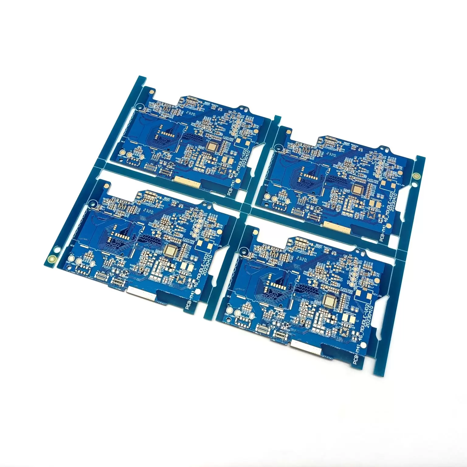
PCB Assembly for Electricity Meter demands careful attention to detail and proven safety practices. Safety incidents often result in immediate component failure, latent damage, or increased warranty claims, which can lead to customer dissatisfaction. Risks such as electrical shock and arc flash may cause injuries or severe burns. By following precise steps, engineers ensure each energy meter operates reliably and safely, protecting both users and equipment from harm.
PCB Assembly for Electricity Meter: Layout and Design
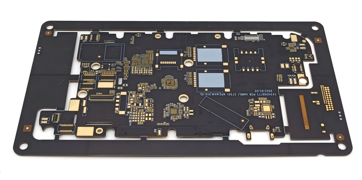
A well-executed pcb assembly for electricity meter projects starts with a robust pcb layout design. Engineers must prioritize safety, measurement accuracy, and long-term reliability. Following industry standards and best practices ensures that each energy meter delivers consistent performance in demanding environments.
Trace Routing for Accuracy
Accurate trace routing forms the backbone of effective pcb layout in electricity meter assemblies. Engineers must separate current-carrying traces from voltage sense traces to prevent unwanted coupling and voltage drops. Proper probe placement and contact design help create low-inductance paths, which reduces measurement errors. The table below highlights key engineering considerations and their impact on measurement accuracy:
| Key Engineering Considerations | Impact on Measurement Accuracy |
|---|
| Probe Placement and Contact Design | Ensures low-inductance paths for voltage sense leads, reducing measurement errors. |
| PCB Stackup and Trace Routing | Separates current-carrying traces from voltage sense traces to avoid coupling and voltage drops. |
| Connector and Component Considerations | Provides accessible sense points adjacent to current terminals for accurate measurements. |
| Test Equipment Calibration | High-precision meters ensure accurate readings, minimizing errors in low-resistance measurements. |

Segregating High and Low Voltage Sections
Segregating high and low voltage sections is essential for safety and compliance. Engineers should maintain adequate spacing between circuits, use curved traces, and select board materials with high dielectric breakdown and Comparative Tracking Index (CTI). The following steps outline best practices for voltage segregation:
●Ensure adequate spacing between high voltage and low voltage circuits according to standards.
●Use curved traces instead of sharp angles.
●Choose board materials with high dielectric breakdown and high CTI.
●Apply conformal coating for additional insulation against contamination.
●Incorporate slots or vertical insulation barriers to address creepage issues.
Isolated Ground Planes for Noise Reduction
Isolated ground planes play a critical role in reducing electrical noise in pcb assembly for electricity meter systems. They provide a low-impedance path for return currents, which minimizes crosstalk and ground bounce. This approach is especially important in high-speed digital circuits, where signal integrity can suffer due to noise.
Best practices for implementing isolated ground planes include:
●Maintain a uniform ground plane to avoid unnecessary splits and gaps.
●Ensure proper return paths to minimize electromagnetic interference (EMI) and crosstalk.
●Avoid creating regions with different blocks of components by not placing splits in the ground plane.
Engineers should also implement unique ground planes for low- and high-voltage sections and ensure separate connections to the power supply for each ground plane. This strategy maintains signal integrity and further reduces noise.
Thermal Management in Energy Meter PCBs
Thermal management is vital for preventing overheating and ensuring the longevity of pcb assembly for electricity meter projects. Effective pcb layout and component placement help dissipate heat efficiently. The following techniques support optimal thermal management:
●Optimize component placement by positioning high-power components away from each other and near the edges for better heat dissipation.
●Use thermal vias to channel heat from hot components to cooler areas or heat sinks, reducing temperatures significantly.
●Select high-thermal-conductivity materials, such as metal-core PCBs, for better heat dissipation in high-power applications.
●Incorporate heat sinks and thermal pads to absorb and dissipate heat, enhancing cooling efficiency.
●Implement cooling methods like forced air, liquid cooling, or passive cooling strategies to manage heat effectively.
The table below summarizes key industry standards for pcb assembly for electricity meter projects:
| Standard | Purpose |
|---|
| IPC-2221 | Guidelines for creepage and clearance distances to reduce ESD risk. |
| IPC-2152 | Recommendations for sizing copper pours and managing current-carrying capacity. |
| IPC-6012 & IPC-A-600 | Defines reliability standards based on performance requirements (class 2 or class 3). |
| UL/IEC standards | Ensures compliance with essential safety requirements across various industries. |
| Safety Essentials | Maintain spacing and isolation, use appropriate insulation materials, integrate protection devices. |
A focus on effective pcb layout, voltage segregation, isolated ground planes, and thermal management ensures that every pcb assembly for electricity meter meets the highest standards for safety, accuracy, and reliability.
Component Selection and Sourcing
High-Quality Materials for Durability
Selecting the right materials ensures the smart meter pcb layout remains reliable over time. Engineers evaluate several criteria to guarantee durability and performance. The table below outlines essential properties for materials used in smart meter pcb schematic designs:
| Criteria | Description |
|---|
| Thermal conductivity (K) | Measures how well the material conducts heat, which helps manage temperature in the smart meter pcb schematic. |
| Coefficient of Thermal Expansion (CTE) | Indicates how much the material expands with temperature changes, preventing interconnection issues. |
| Dielectric constant (Er or Dk) | Affects signal integrity and impedance, which is vital for high-frequency smart meter pcb schematic circuits. |
| Loss tangent (tanδ) | Lower values mean less dielectric loss, improving high-frequency performance. |
| Moisture absorption | Lower absorption increases durability, especially in humid environments. |
| CAF resistance | Prevents conductive anodic filament formation, reducing the risk of smart meter pcb schematic failures. |
Sourcing for Energy Applications
Component sourcing for energy meter projects requires careful attention to function and reliability. The following table lists key components and their roles in monitoring energy consumption:
| Component | Function |
|---|
| Voltage Sensor | Measures voltage in the system for accurate energy consumption tracking. |
| Current Sensor | Tracks current flow, which is essential for calculating consumption. |
| Shunt | Enables precise current measurement, improving consumption accuracy. |
| Data Processing Unit | Processes sensor data and calculates energy consumption. |
| Wired Communication | Provides reliable data transmission for smart meter pcb schematic integration. |
| Wireless Communication | Supports flexible remote monitoring in smart meter pcb layout designs. |
Managing Tolerances and Ratings
Engineers must select components with proper tolerances and ratings to ensure accurate consumption measurement. For high-speed smart meter pcb schematic circuits, tolerances of ±5% are common, while power boards may use ±15%. The IPC classification system guides quality:
●IPC Class 1: General electronic products, suitable for basic smart meter pcb schematic needs.
●IPC Class 2: Dedicated service products, ideal for smart meter pcb layout requiring high performance.
●IPC Class 3: High reliability, used in critical smart meter pcb schematic applications.
Tolerance mismatches can cause:
- Signal accuracy issues, leading to incorrect consumption readings.
- Frequency response errors in filters, affecting smart meter pcb schematic performance.
- Increased power consumption, reducing efficiency.
DIY Smart Meter PCB: Choosing Components
DIY smart meter pcb projects require careful component selection for safety and accuracy. Consider the following:
●Choose current and voltage sensors that match household specifications for precise consumption tracking.
●Select microcontroller options like ESP32 for smart meter pcb programming, which offers strong community support.
●Buy passive components in bulk for cost savings in smart meter pcb schematic builds.
●Use power supply modules with overcurrent protection to safeguard the smart meter pcb schematic.
●Avoid aging components and ensure consistent quality for all smart meter pcb schematic parts.
●Place components thoughtfully in the smart meter pcb layout, such as positioning capacitors near power chips.
●Do not mix components from different brands to maintain smart meter pcb schematic reliability.
Assembly Techniques and Best Practices
Assembly Order: Small to Large Components
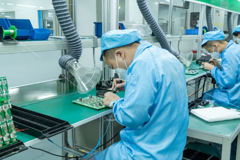
A well-organized assembly process improves the reliability of every energy meter. Technicians often follow a specific order to minimize errors and ensure strong solder joints. The recommended steps include:
1.Align the PCB properly on the conveyor during wave soldering to prevent uneven solder distribution.
2.Inspect solder joints for a shiny, smooth, conical shape to confirm solid connections.
3.Use automated optical inspection (AOI) systems to detect misaligned components or insufficient solder.
4.Perform electrical testing to verify functionality and check the impedance of critical traces.
5.Clean the PCB to remove flux residue or contaminants before final assembly.
6.Apply conformal coating for environmental protection, especially if the meter will face moisture or dust.
A reliable assembly process ensures consistent and stable solder joints, which are essential for long-term performance.
Soldering Methods and IPC Standards
Proper soldering techniques play a vital role in preventing common defects during assembly. Technicians encounter issues such as solder bridges, cold solder joints, and insufficient solder. They can prevent these problems by optimizing stencil thickness, maintaining clean pads, and following recommended reflow profiles. Regular calibration of placement machines and the use of vision alignment systems help avoid component misalignment. Technicians also rely on IPC standards to guide soldering time and temperature, which reduces the risk of lifted pads or traces. Automated optical inspection verifies correct component placement, while high-Tg materials and controlled reflow temperatures prevent PCB warpage.
Handling Sensitive and High-Voltage Parts
Safety remains a top priority when handling sensitive or high-voltage parts during assembly. The table below outlines essential precautions:
| Precaution | Description |
|---|
| Insulated Gloves | Always wear insulated gloves to prevent electric shock or damage. |
| Avoid Live Equipment | Do not work on live equipment unless necessary. |
| Safety When Measuring | Use insulation gloves when measuring in high-voltage environments. |
Technicians who follow these precautions protect themselves and maintain the integrity of the assembly process.
Safety and Compliance in Energy Meter Assembly
Meeting Regulatory and IPC Standards
Engineers must follow strict safety standards when assembling an energy meter. These standards help ensure reliable operation and user safety. The table below lists important regulatory and IPC standards that guide the assembly process:
| Standard | Description |
|---|
| IPC–A-600 | Describes the target, acceptable, and nonconforming conditions on printed circuit boards. |
| IPC-A–6012 | Specifies the performance and qualification requirements for rigid PCB fabrication. |
| IPC-A-610 | Regulates the acceptability of electronic assemblies, commonly used for inspection. |
| IPC-A-620 | Recommends practices and requirements for cable manufacturing, wire, and harness assemblies. |
| IPC-A-630 | Provides an acceptability standard for manufacturing, inspection, and testing electronic enclosures. |
| ISO 9000 | Details quality and reliability requirements for PCB design, manufacturing, and testing. |
| FDA 21CFR820 | Outlines manufacturing and quality system regulation requirements for medical devices. |
These safety standards set clear expectations for quality, reliability, and inspection. They also help engineers avoid common mistakes during assembly.
Isolation and Protection Features
Proper isolation and protection features are essential for compliance with safety standards. Engineers must measure creepage and clearance distances to prevent arcing and tracking. They select materials that can withstand high voltages, since standard FR4 may not provide enough protection. Environmental factors, such as pollution and altitude, affect the required distances for safety. Key safety standards like IEC 60664-1, IEC 62368-1, and IPC-2221A define these requirements. Engineers also consider the pollution degree and choose higher-grade laminates when needed. These steps help maintain safety and ensure the meter meets all protection requirements.
Safe Handling of High-Voltage Sections
Safe handling of high-voltage sections protects both the assembly team and the final product. Engineers route high-voltage traces away from sensitive components to prevent arcing. They maintain strict clearance and creepage distances, especially in designs above 1000V. Physical barriers, such as slots or cutouts, increase creepage distances and improve safety. Testing the dielectric strength of PCB materials ensures they meet safety standards. Engineers place heat-generating parts in well-ventilated areas to avoid thermal buildup. Consistent spacing rules across all high-voltage nets prevent weak points. Sensitive components stay isolated from high-voltage areas, which reduces interference. Calculating creepage distances based on environmental conditions helps avoid surface discharges. Engineers add safety margins to account for manufacturing tolerances. They avoid packing components too closely, which ensures enough space for safety and protection.
Testing, Calibration, and Integration
Functional Testing for Energy Monitoring System
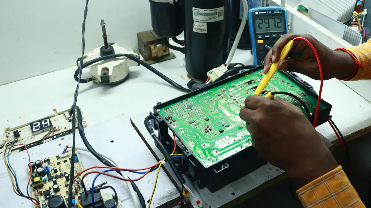
Engineers begin by performing functional testing on the energy monitoring system. They verify that each system component works as intended. The process checks the accuracy of data collection, transmission, and storage. Engineers simulate different load conditions to see how the system responds. They monitor real-time data to confirm that the system captures and processes information without delay. The team also tests the system’s ability to detect faults and report errors. This step ensures that the energy monitoring system provides reliable data for users and operators.
Calibration for Measurement Accuracy
Calibration remains a critical step for any energy monitoring system. Engineers use several methods to achieve precise measurement. The table below summarizes the most effective calibration methods for an energy meter:
| Calibration Method | Description |
|---|
| Direct comparison method | Compare the meter to be calibrated with a standard meter to judge its error. |
| Standard resistance method | Use standard resistance for calibration to judge the meter's error. |
| Standard voltage method | Use standard voltage for calibration to judge the meter's error. |
| Standard current method | Use standard current for calibration to judge the meter's error. |
Engineers select the method that best matches the system requirements. They adjust the system until the data matches the reference values. Accurate calibration ensures that the energy monitoring system delivers trustworthy data for billing and analysis.
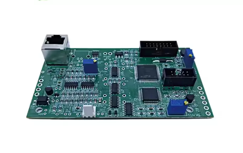
Final Inspection and Documentation
The final inspection covers every part of the energy monitoring system. Engineers review solder joints, component placement, and wiring. They confirm that the system meets all safety and performance standards. The team records all testing and calibration results in detailed documentation. This record includes data logs, calibration certificates, and system configuration files. Proper documentation supports future maintenance and troubleshooting. Before integration and installation, engineers verify that the system can deliver real-time data to the monitoring platform. This step completes the integration and installation process, ensuring that the energy monitoring system operates smoothly from the start.
Successful assembly of a meter PCB requires careful planning and attention to detail. Each step, from layout to testing, supports safety and accuracy in every energy application. Readers should:
●Follow proven assembly techniques.
●Select quality components.
●Meet all safety standards.
Applying these best practices helps ensure reliable operation. For more information, readers can explore industry guidelines or consult experts.
About the author:

Sonic Yang
As a major in Electronics and Mechanical Automation, Sonic has been engaged in PCB design, R&D, and manufacturing of electronics for around 22 years, as the engineering director, and coordinates with the supply chain(components and CNC parts), providing professional support and consulting for global customers.
 en
en


 WhatsApp